


PowerSPAN II PCI Bus Bridge
Memory Map and Devices
5 - 12
PPC/PMC-8260/DS1
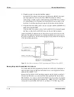
Opening More Windows in the PCI Target Channel
The PCI target channel needs to be programmed to make the resources on the 60x
bus side visible on the PCI bus i.e. to enable the PCI bus to access devices on the
60x bus. By default, one window of four possible windows is activated by the
default settings in the E
2
PROM. To activate more windows, program the other PCI
target images (P1_TI1_CTL to P1_TI3_CTL) in the firmware of the carrier board.
Program the registers of the PCI target images according to the instructions below.
P1_TIx_CTL
Define basic attributes and sizes for the base address registers. These settings must
be accomplished while PCI lockout is active. The following settings in
P1_TIx_CTL must be programmed:
1. Set bit BAR_EN to 1 to enable BAR in PCI configuration header
2. Set bit MODE to 0 to map BAR to PCI memory space, or to 1 for PCI
I/O space
3. Set bit BS to define the size of translation image
4. Optional: Set bit P1_BSTx[PRFTCH] to enable read prefetching
P1_BSTx
Configure the PCI base address by programming P1_BSTx. This setting is usually
performed by the PCI bus enumerator of the host which assigns PCI resources to all
PCI devices.
P1_TIx_TADDR
Configure the 60x bus base address by programming P1_TIx_TADDR. For further
information, see the
PowerSpan II User Manual
.
P1_TIx_CTL
Set the following additional attribute bits and the size of the target image in
P1_TIx_CTL:
•
Image and translation enable/disable
•
Caching attributes
Setting the bit GBL enforces cache coherency on the 60x bus. Cache Inhibit
(CI) is not supported on the PPC/PMC-8260/DS1.
•
Read prefetching attributes
Defines whether to keep or purge prefetched data and the amount of data
prefetched
Summary of Contents for PPC/PMC-8260/DS1
Page 1: ...PPC PMC 8260 DS1 Reference Guide P N 6806800B10A July 2006 ...
Page 8: ...viii PPC PMC 8260 DS1 ...
Page 22: ...xxii PPC PMC 8260 DS1 ...
Page 26: ...xxvi PPC PMC 8260 DS1 ...
Page 30: ...xxx PPC PMC 8260 DS1 ...
Page 31: ...1 Introduction ...
Page 32: ......
Page 39: ...2 Installation ...
Page 40: ......
Page 53: ...3 Indicators and Connectors ...
Page 54: ......
Page 64: ...On Board Connectors Indicators and Connectors 3 12 PPC PMC 8260 DS1 ...
Page 65: ...4 Firmware ...
Page 66: ......
Page 104: ...Code Examples Firmware 4 40 PPC PMC 8260 DS1 ...
Page 105: ...5 Memory Map and Devices ...
Page 106: ......
Page 132: ...Resetting the Devices Memory Map and Devices 5 28 PPC PMC 8260 DS1 ...
Page 133: ...6 TDM Channel Configuration ...
Page 134: ......
Page 145: ...A Troubleshooting ...
Page 146: ......
Page 148: ...A 4 PPC PMC 8260 DS1 ...
Page 150: ...I 2 PPC PMC 8260 DS1 ...