


Indicators and Connectors
3 - 6
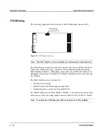
PPC/PMC-8260/DS1
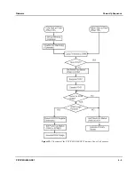
POST running
SDRAM test running
Yellow flashing
Off
SSRAM test running
Off
Yellow flashing
PowerSpan test running
Yellow
Off
Framer #1 test running
Off
Yellow
Framer #2 test running
Yellow
Off
Framer #3 test running
Off
Yellow
Framer #4 test running
Yellow
Off
T8105 test running
Off
Yellow
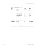
POST complete
Yellow
Green
Executing ROM image (end of boot sequence)
Green
Off
Primary booter
Idle loop
Red
Green (dimmed
flashing)
Flash erase/write operation
ongoing
Red
Yellow (flashing)
Before execution of uploaded
image
Green
Off
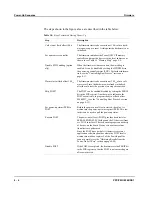
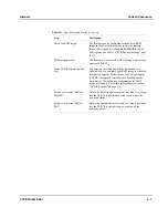
Table 9:
LED States During Power Up (cont.)
State
LED 1
LED 2
Summary of Contents for PPC/PMC-8260/DS1
Page 1: ...PPC PMC 8260 DS1 Reference Guide P N 6806800B10A July 2006 ...
Page 8: ...viii PPC PMC 8260 DS1 ...
Page 22: ...xxii PPC PMC 8260 DS1 ...
Page 26: ...xxvi PPC PMC 8260 DS1 ...
Page 30: ...xxx PPC PMC 8260 DS1 ...
Page 31: ...1 Introduction ...
Page 32: ......
Page 39: ...2 Installation ...
Page 40: ......
Page 53: ...3 Indicators and Connectors ...
Page 54: ......
Page 64: ...On Board Connectors Indicators and Connectors 3 12 PPC PMC 8260 DS1 ...
Page 65: ...4 Firmware ...
Page 66: ......
Page 104: ...Code Examples Firmware 4 40 PPC PMC 8260 DS1 ...
Page 105: ...5 Memory Map and Devices ...
Page 106: ......
Page 132: ...Resetting the Devices Memory Map and Devices 5 28 PPC PMC 8260 DS1 ...
Page 133: ...6 TDM Channel Configuration ...
Page 134: ......
Page 145: ...A Troubleshooting ...
Page 146: ......
Page 148: ...A 4 PPC PMC 8260 DS1 ...
Page 150: ...I 2 PPC PMC 8260 DS1 ...