


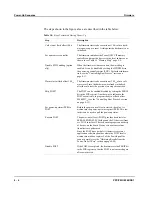
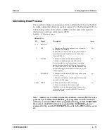


Power-Up Sequence
Firmware
4 - 4
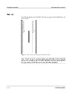
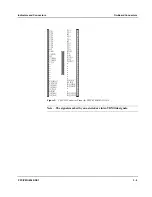
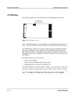
PPC/PMC-8260/DS1
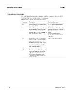
Power-Up Sequence
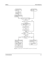
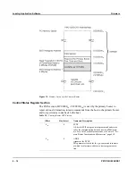
At power up, the CPU starts firmware code execution at address 100
16
and the
watchdog timer and the bus monitor are enabled to prevent a reset or a system
hang. One of the first things it does is to map the boot flash device to address
FE000000
16
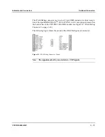
and to continue code execution there. The following flow chart shows
an overview of the steps performed by the firmware and also the steps which can be
controlled by a driver.
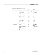
Note: The PMC8260/DS1 firmware does not display any banner or prompt
on a terminal connected to the serial debug ports. The firmware has no shell,
therefore it cannot accept commands from a terminal. Only the front panel
LEDs show the current status of the boot process, the power-on self-test and
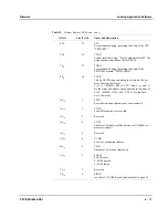
the primary booter (see Table 9 “LED States During Power Up” page 3-5).
Summary of Contents for PPC/PMC-8260/DS1
Page 1: ...PPC PMC 8260 DS1 Reference Guide P N 6806800B10A July 2006 ...
Page 8: ...viii PPC PMC 8260 DS1 ...
Page 22: ...xxii PPC PMC 8260 DS1 ...
Page 26: ...xxvi PPC PMC 8260 DS1 ...
Page 30: ...xxx PPC PMC 8260 DS1 ...
Page 31: ...1 Introduction ...
Page 32: ......
Page 39: ...2 Installation ...
Page 40: ......
Page 53: ...3 Indicators and Connectors ...
Page 54: ......
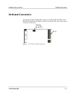
Page 64: ...On Board Connectors Indicators and Connectors 3 12 PPC PMC 8260 DS1 ...
Page 65: ...4 Firmware ...
Page 66: ......
Page 104: ...Code Examples Firmware 4 40 PPC PMC 8260 DS1 ...
Page 105: ...5 Memory Map and Devices ...
Page 106: ......
Page 132: ...Resetting the Devices Memory Map and Devices 5 28 PPC PMC 8260 DS1 ...
Page 133: ...6 TDM Channel Configuration ...
Page 134: ......
Page 145: ...A Troubleshooting ...
Page 146: ......
Page 148: ...A 4 PPC PMC 8260 DS1 ...
Page 150: ...I 2 PPC PMC 8260 DS1 ...