Serial Interconnections
A-4
User’s Manual
A
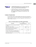
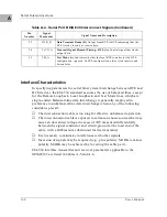
The MVME162 conforms to EIA-232-D specifications. Note that although the
EIA-232-D standard recommends the use of short interconnection cables not
more than 50 feet (15m) in length, longer cables are permissible provided the
total load capacitance measured at the interface point and including signal
terminator does not exceed 2500pF.
EIA-530 Connections
The EIA-530 interface complements the EIA-232-D interface in function. The
EIA-530 standard defines the mechanical aspects of this interface, which is
used for transmission of serial binary data, both synchronous and
asynchronous. It is adaptable to balanced (double-ended) as well as
unbalanced (single-ended) signaling and offers the possibility of higher data
rates than EIA-232-D with the same DB25 connector.
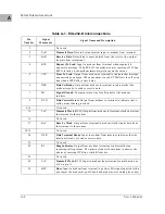
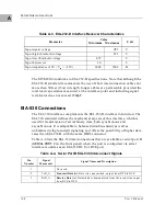
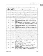
Table A-4 lists the EIA-530 interconnections that are available at serial port B
(
SERIAL PORT 2
on the front panel) when the port is configured via serial
interface modules as an EIA-530 DCE or DTE port.
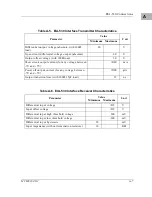
Table A-3. EIA-232-D Interface Receiver Characteristics
Parameter
Value
Minimum Maximum
Unit
Input signal voltage
±
25
V
Input high threshold voltage
2.25
V
Input low threshold voltage
0.75
V
Input hysteresis
1.0
V
Input impedance (-15V < V
in
< +15V)
3000
7000
Ω
Table A-4. Serial Port B EIA-530 Interconnect Signals
Pin
Number
Signal
Mnemonic
Signal Name and Description
1
Not used.
2
TxD_A
Transmit Data (A).
Data to be transmitted; output from DTE to DCE.
3
RxD_A
Receive Data (A).
Data which is demodulated from the receive line; input
from DCE to DTE.
Summary of Contents for MVME162
Page 1: ...MVME162 Embedded Controller User s Manual MVME162 D2 ...
Page 6: ......
Page 10: ...x ...
Page 12: ...xii ...
Page 14: ...xiv ...
Page 52: ...Hardware Preparation and Installation 2 26 MVME162 Embedded Controller User s Manual 2 ...
Page 64: ...Operating Instructions 3 12 User s Manual 3 This page intentionally left blank ...
Page 78: ...Operating Instructions 3 26 User s Manual 3 ...
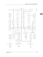
Page 92: ...Functional Description 4 14 User s Manual 4 Figure 4 1 MVME162 Main Module Block Diagram ...

