Hardware Preparation
MVME162/D2
2-7
2
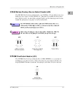
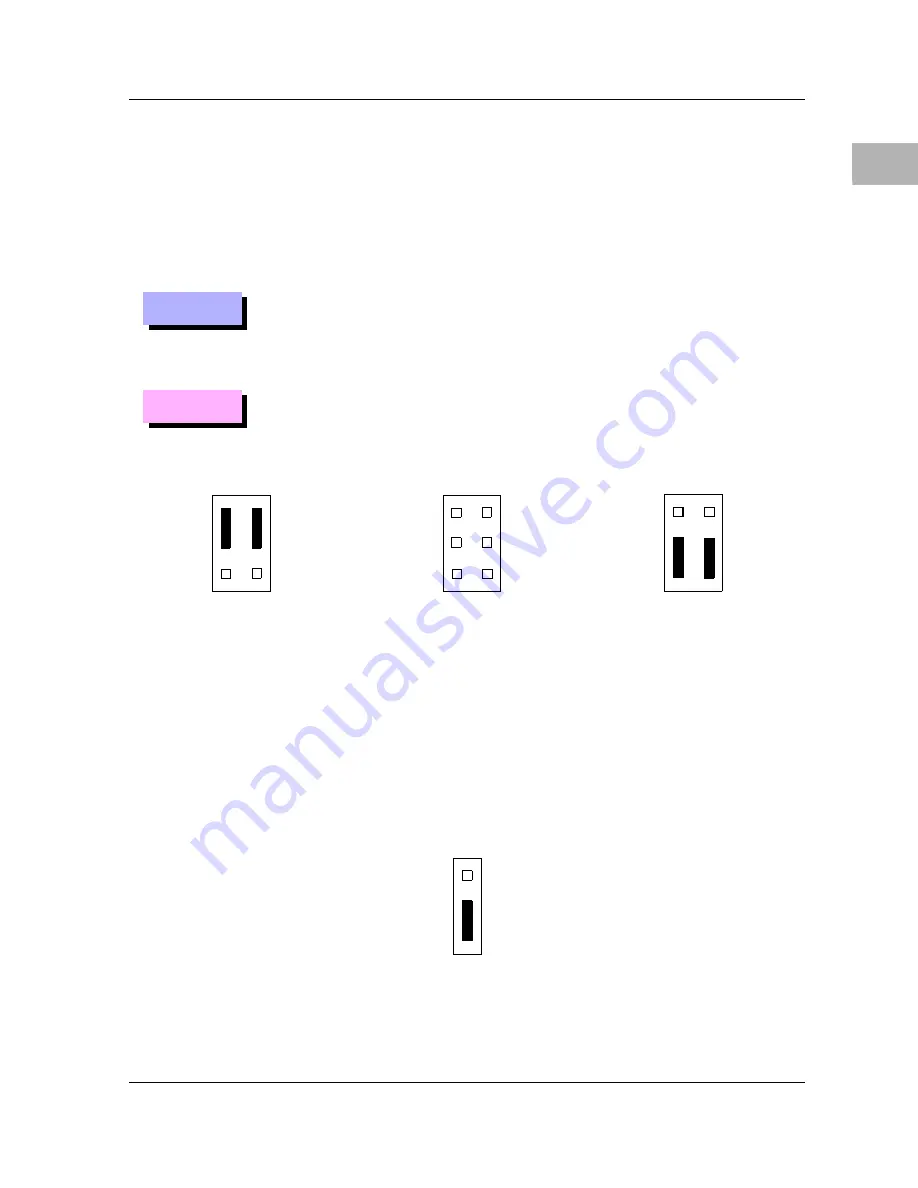
SRAM Battery Backup Source Select Header (J20)
The MVME162 is factory-configured to use 5V standby power as a
backup power source for the SRAM (i.e., jumpers are installed across pins 1
and 3 and 2 and 4). To select the onboard battery as the backup power source,
install the jumpers across pins 3 and 5 and 4 and 6.
N
ote
For MVME162s without the optional VMEbus interface (i.e.,
without the VMEchip2 ASIC), you must select the onboard
battery as the backup power source.
C
aution
Removing all jumpers may temporarily disable the SRAM.
Do not remove all jumpers from J20, except for storage.
EPROM Size Select Header (J21)
The MVME162 is factory-configured for a 4Mbit EPROM (i.e., a jumper is
installed across pins 2 and 3). This is the only size currently available; if a
larger EPROM becomes available, this jumper will allow it to be selected.
(Factory configuration)
5V STBY
J20
2
1
6
5
J20
2
1
6
5
J20
2
1
Backup Power Disabled
Onboard Battery
6
5
(For storage only)
1
2
3
(Factory configuration)
J21
4Mbit EPROM
Summary of Contents for MVME162
Page 1: ...MVME162 Embedded Controller User s Manual MVME162 D2 ...
Page 6: ......
Page 10: ...x ...
Page 12: ...xii ...
Page 14: ...xiv ...
Page 52: ...Hardware Preparation and Installation 2 26 MVME162 Embedded Controller User s Manual 2 ...
Page 64: ...Operating Instructions 3 12 User s Manual 3 This page intentionally left blank ...
Page 78: ...Operating Instructions 3 26 User s Manual 3 ...
Page 92: ...Functional Description 4 14 User s Manual 4 Figure 4 1 MVME162 Main Module Block Diagram ...

