MVME162/D23-1
3
OPERATING
INSTRUCTIONS
Introduction
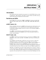
This chapter provides information necessary to use the MVME162 in a system
configuration. This includes a description of the switches and LEDs, memory
maps, and software initialization of the module.
Switches and LEDs
The MVME162 front panel has
ABORT
and
RESET
switches and eight LED
(light-emitting diode) indicators (
FAIL
,
STAT
,
RUN
,
SCON
,
LAN
,
FUSE
,
SCSI
,
VME
).
ABORT Switch (S1)
When enabled by software, the
ABORT
switch generates an interrupt at a user-
programmable level. It is normally used to abort program execution and
return to the 162Bug debugger firmware located in the MVME162 EPROM
and Flash memory.
The
ABORT
switch interrupter in the MCchip ASIC is an edge-sensitive
interrupter connected to the
ABORT
switch. This interrupter is filtered to
remove switch bounce.
RESET Switch (S2)
The
RESET
switch resets all onboard devices; it also drives
SYSRESET
* if the
MVME162 is the system controller. The RESET switch may be disabled by
software.
The VMEchip2 includes both a global and a local reset driver. When the
VMEchip2 operates as the VMEbus system controller, the reset driver
provides a global system reset by asserting the VMEbus signal
SYSRESET
*. A
SYSRESET
* may be generated by the
RESET
switch, a power-up reset, a
watchdog timeout, or by a control bit in the LCSR in the VMEchip2.
SYSRESET
*
remains asserted for at least 200 ms, as required by the VMEbus specification.
Similarly, the VMEchip2 provides an input signal and a control bit to initiate
a local reset operation. By setting a control bit, software can maintain a board
in a reset state, disabling a faulty board from participating in normal system
operation. The local reset driver is enabled even when the VMEchip2 is not the
Summary of Contents for MVME162
Page 1: ...MVME162 Embedded Controller User s Manual MVME162 D2 ...
Page 6: ......
Page 10: ...x ...
Page 12: ...xii ...
Page 14: ...xiv ...
Page 52: ...Hardware Preparation and Installation 2 26 MVME162 Embedded Controller User s Manual 2 ...
Page 64: ...Operating Instructions 3 12 User s Manual 3 This page intentionally left blank ...
Page 78: ...Operating Instructions 3 26 User s Manual 3 ...
Page 92: ...Functional Description 4 14 User s Manual 4 Figure 4 1 MVME162 Main Module Block Diagram ...

