Serial Interconnections
A-6
User’s Manual
A
Interface Characteristics
In specifying parameters for serial binary data interchange between DTE and
DCE devices, the EIA-530 standard assumes the use of balanced lines, except
for the Remote Loopback, Local Loopback, and Test Mode lines, which are
single-ended. Balanced-line data interchange is generally employed in
preference to unbalanced-line data interchange where any of the following
conditions prevail:
❏
The interconnection cable is too long for effective unbalanced operation.
❏
The interconnection cable is exposed to extraneous noise sources that may
cause an unwanted voltage in excess of
±
1V measured differentially
between the signal conductor and circuit ground at the load end of the
cable, with a 50
Ω
resistor substituted for the transmitter.
❏
It is necessary to minimize interference with other signals.
❏
Inversion of signals may be required (e.g., plus polarity MARK to minus
polarity MARK may be achieved by inverting the cable pair).
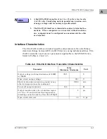
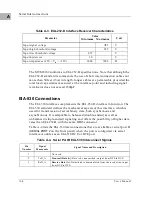
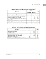
EIA-530 interface transmitter and receiver parameters applicable to the
MVME162 are listed in Tables A-5 and A-6.
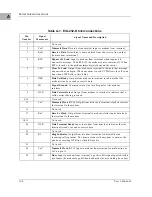
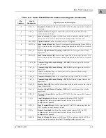
23
DTR_B
Data Terminal Ready (B).
Output from DTE to DCE indicating that the
DTE is ready to send or receive data.
24
TxCO_A
Transmit Signal Element Timing—DTE (A).
Control signal that clocks
output data.
25
TM_A
Test Mode (A).
Indicates whether the local DCE is under test. In DTE
configuration, ignored. In DCE configuration, always tied inactive and
driven false.
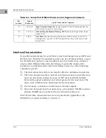
Table A-4. Serial Port B EIA-530 Interconnect Signals (Continued)
Pin
Number
Signal
Mnemonic
Signal Name and Description
Summary of Contents for MVME162
Page 1: ...MVME162 Embedded Controller User s Manual MVME162 D2 ...
Page 6: ......
Page 10: ...x ...
Page 12: ...xii ...
Page 14: ...xiv ...
Page 52: ...Hardware Preparation and Installation 2 26 MVME162 Embedded Controller User s Manual 2 ...
Page 64: ...Operating Instructions 3 12 User s Manual 3 This page intentionally left blank ...
Page 78: ...Operating Instructions 3 26 User s Manual 3 ...
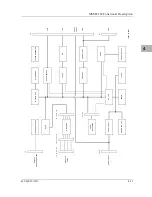
Page 92: ...Functional Description 4 14 User s Manual 4 Figure 4 1 MVME162 Main Module Block Diagram ...

