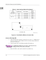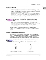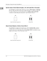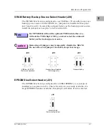
Hardware Preparation and Installation
2-8
MVME162 Embedded Controller User’s Manual
2
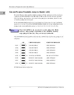
General-Purpose Readable Jumpers Header (J22)
Header J22 provides eight readable jumpers. These jumpers can be read as a
register (at $FFF4202D) in the MCchip LCSR (local control/status register).
The bit values are read as a zero when the jumper is installed, and as a one
when the jumper is removed.
If the MVME162BUG firmware is installed, four jumpers are user-definable
(pins 1-2, 3-4, 5-6, 7-8). If the MVME162BUG firmware is not installed, seven
jumpers are user-definable (pins 1-2, 3-4, 5-6, 7-8, 11-12, 13-14, 15-16).
N
ote
Pins 9-10 (GPIO3) are reserved to select either the Flash
memory map (jumper installed) or the EPROM memory
map (jumper removed). They are not user-definable.
The MVME162 is shipped from the factory with J22 set to all zeros (jumpers on
all pins).
J22
15
GPIO7
GPIO6
GPIO5
GPIO1
GPIO4
GPIO3
GPIO2
1
2
16
GPIO0
EPROMs Selected (factory configuration)
USER-DEFINABLE
USER-DEFINABLE
USER-DEFINABLE
REFER TO 162BUG MANUAL
USER-DEFINABLE
IN=FLASH; OUT=EPROM
REFER TO 162BUG MANUAL
REFER TO 162BUG MANUAL
162BUG INSTALLED
USER-DEFINABLE
USER-DEFINABLE
USER-DEFINABLE
USER-DEFINABLE
USER-DEFINABLE
IN=FLASH; OUT=EPROM
USER-DEFINABLE
USER-DEFINABLE
USER CODE INSTALLED
9
10
Summary of Contents for MVME162
Page 1: ...MVME162 Embedded Controller User s Manual MVME162 D2 ...
Page 6: ......
Page 10: ...x ...
Page 12: ...xii ...
Page 14: ...xiv ...
Page 52: ...Hardware Preparation and Installation 2 26 MVME162 Embedded Controller User s Manual 2 ...
Page 64: ...Operating Instructions 3 12 User s Manual 3 This page intentionally left blank ...
Page 78: ...Operating Instructions 3 26 User s Manual 3 ...
Page 92: ...Functional Description 4 14 User s Manual 4 Figure 4 1 MVME162 Main Module Block Diagram ...

