Memory Maps
MVME162/D2
3-5
3
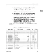
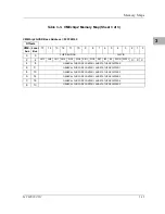
5. The EPROM and Flash are sized by the MCchip ASIC from an
8-bit private bus to the 32-bit MPU local bus. Because the
device size is less than the allocated memory map for some
entries, the device contents repeat for those entries.
If jumper GPIO3 is installed, the Flash device is accessed. If
GPIO3 is not installed, the EPROM is accessed.
6. The Flash and EPROM are sized by the MCchip ASIC from an
8-bit private bus to the 32-bit MPU local bus. Because the
device size is less than the allocated memory map for some
entries, the device contents repeat for those entries.
If jumper GPIO3 is installed, the PROM device is accessed. If
GPIO3 is not installed, the Flash is accessed.
7. These areas are not decoded unless one of the programmable
decoders are initialized to decode this space. If they are not
decoded, an access to this address range will generate a local
bus timeout. The local bus timer must be enabled.
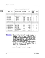
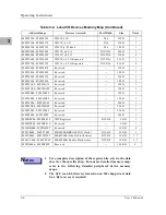
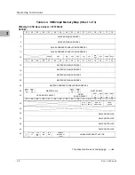
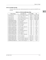
Table 3-2 focuses on the ‘‘Local I/O Devices’’ portion of the local bus main
memory map.
Table 3-2. Local I/O Devices Memory Map
Address Range
Devices Accessed
Port Width
Size
Notes
$FFF00000 - $FFF3FFFF
Reserved
- -
256 KB
4
$FFF40000 - $FFF400FF
VMEchip2 (LCSR)
D32
256 B
1, 3
$FFF40100 - $FFF401FF
VMEchip2 (GCSR)
D32-D8
256 B
1, 3
$FFF40200 - $FFF40FFF
Reserved
- -
3.5 KB
4, 5
$FFF41000 - $FFF41FFF
Reserved
- -
4 KB
4
$FFF42000 - $FFF42FFF
MCchip
D32-D8
4 KB
1
$FFF43000 - $FFF44FFF
Reserved
- -
8 KB
4
$FFF45000 - $FFF45800
SCC #1 (Z85230)
D8
2 KB
1, 2
$FFF45801 - $FFF45FFF
SCC #2 (Z85230)
D8
2 KB
1, 2
$FFF46000 - $FFF46FFF
LAN (82596CA)
D32
4 KB
1, 6
$FFF47000 - $FFF47FFF
SCSI (53C710)
D32-D8
4 KB
1
$FFF48000 - $FFF57FFF
Reserved
- -
64 KB
4
$FFF58000 - $FFF5807F
IPIC IP_a I/O
D16
128 B
1
$FFF58080 - $FFF580FF
IPIC IP_a ID
D16
128 B
1
$FFF58100 - $FFF5817F
IPIC IP_b I/O
D16
128 B
1
$FFF58180 - $FFF581FF
IPIC IP_b ID Read
D16
128 B
1
$FFF58200 - $FFF5827F
IPIC IP_c I/O
D16
128 B
1
Summary of Contents for MVME162
Page 1: ...MVME162 Embedded Controller User s Manual MVME162 D2 ...
Page 6: ......
Page 10: ...x ...
Page 12: ...xii ...
Page 14: ...xiv ...
Page 52: ...Hardware Preparation and Installation 2 26 MVME162 Embedded Controller User s Manual 2 ...
Page 64: ...Operating Instructions 3 12 User s Manual 3 This page intentionally left blank ...
Page 78: ...Operating Instructions 3 26 User s Manual 3 ...
Page 92: ...Functional Description 4 14 User s Manual 4 Figure 4 1 MVME162 Main Module Block Diagram ...

