Hardware Preparation and Installation
2-4
MVME162 Embedded Controller User’s Manual
2
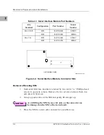
Figure 2-2. Serial Interface Module, Connector Side
Removal of Existing SIM
1.
Each serial interface module is retained by two 4-40 x
3
/
16
” Phillips-head
screws in opposite corners. Remove the two screws and store them in a
safe place for later use.
2.
Grasp opposite sides of the SIM and gently lift straight up.
C
aution
Avoid lifting the SIM by one side only, as the connector can
be damaged on the SIM or the main board.
3.
Place the SIM in a static-safe container for possible reuse.
Table 2-1. Serial Interface Module Part Numbers
EIA
Standard
Configuration
Part Number
Model
Number
EIA-232-D
DTE
01-W3846B
SIM05
DCE
01-W3865B
SIM06
EIA-530
DTE
01-W3868B
SIM07
DCE
01-W3867B
SIM08
10922.00 9403 (2-2)
SECONDARY SIDE
39
1
40
2
J1
Summary of Contents for MVME162
Page 1: ...MVME162 Embedded Controller User s Manual MVME162 D2 ...
Page 6: ......
Page 10: ...x ...
Page 12: ...xii ...
Page 14: ...xiv ...
Page 52: ...Hardware Preparation and Installation 2 26 MVME162 Embedded Controller User s Manual 2 ...
Page 64: ...Operating Instructions 3 12 User s Manual 3 This page intentionally left blank ...
Page 78: ...Operating Instructions 3 26 User s Manual 3 ...
Page 92: ...Functional Description 4 14 User s Manual 4 Figure 4 1 MVME162 Main Module Block Diagram ...

