background image

54

M16 Camera Manual: Installation

Notes

After you have connected an MxBus module, you need to activate it in the camera's 
browser interface (

Admin Menu > Manage Hardware Expansions or Manage MxBus 

Modules, respectively).

2.2.8  Closing the Camera Housing

Once you have completed the tasks in the interior of the M16, you need to reassemble the 
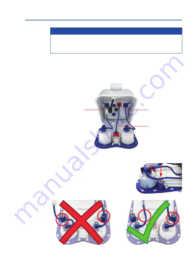
front element of the M16. Make sure that you are reconnecting all plugs as shown in the 
figure if you removed any of them:

Procedure

1.  Before inserting the front element, make sure that 

the sensor module cables of both image sensors are 
running at the 

inside

 of the screw bore (see red arrow). 

The sensor cables must not run along the outside 

of the screw bores (see figure below)!

Sensor module cable 

right

Sensor module cable 

left

I/O cable to front ele-

ment (red clips!)

Summary of Contents for AllroundDual M16B

Page 1: ...Camera Manual AllroundDual M16 33 068 002_EN_09 2020 ...

Page 2: ...2 M16 Camera Manual ...

Page 3: ...era Day Night 26 1 5 AvailableAccessories 27 1 5 1 Polarization Filter 27 1 5 2 MiniUSB Cable to MiniUSB Angled Straight 27 1 5 3 MiniUSB Cable to MiniUSB Angled Angled 27 1 5 4 MiniUSB Cable to USB A Socket 27 1 5 5 Ethernet Patch Cable for Bayonet Catch 28 1 5 6 NPA PoE Set 28 1 5 7 MX Overvoltage Protection Box 28 1 5 8 MX NPA Box 29 1 5 9 MX GPS Box 29 1 5 10 MX 232 IO Box 29 1 5 11 ExtIO Expa...

Page 4: ...al Not Required for M16 Complete Cameras 48 2 2 4 Exchanging Sensor Modules 49 2 2 5 Replacing the Ethernet Patch Cable 50 2 2 6 Connecting a USB Cable 52 2 2 7 Connecting a Two Wire MxBus Cable 53 2 2 8 Closing the Camera Housing 54 2 3 MountingtheCamerawithWallMount 56 2 3 1 VarioFlex Wall Mount 56 2 4 MountingtheCamerawithCeilingMount 60 2 4 1 VarioFlex Ceiling Mount 60 2 5 MountingtheCamerawit...

Page 5: ...on 106 3 5 2 Formatting the MicroSD Card 108 3 5 3 Activating Recording 109 3 5 4 Accessing Data on the MicroSD Card 110 3 5 5 Deactivating Card Recording 110 3 5 6 Using a MicroSD Card in a Different MOBOTIX Camera 111 3 5 7 Limitations on Warranty When Using Flash Storage Media 111 3 6 ConfigurationintheBrowser 112 3 6 1 Overview 112 3 6 2 General Browser Settings 114 3 6 3 Configuring the M16 T...

Page 6: ...DeniedPersonsList seewww bis doc gov Policy Guidance Lists of Parties of Concern https www treasury gov resource center sanctions sdn list pages default aspx Under no circumstances must the camera itself or its thermal image sensors be used inthedesign thedevelopmentorintheproductionofnuclear biologicalorchemical weapons or in the weapons themselves Legal aspects of video and sound recording You m...

Page 7: ...lso protects the building and the whole network infrastructure Max power consumption of attached extension modules The power consumption of all attached MxBus modules must not exceed 3W When attaching modules to the MxBus connector and the USB socket the power consumption of all attached modules must not exceed 4W if the camera is powered by PoE class 3 If PoE class 2 is used the cam era cannot po...

Page 8: ...with a Day and a Night sensor module the camera will automatically switch to the appropriate image sensor depending on the illumination The introduction of the newest sensor technology with increased light sensitivity in combi nation with the new HD Premium lenses aperture f 1 8 not only generates more brilliant images with up to 3072x2048 it also delivers color images of higher quality under lowl...

Page 9: ...9 ...

Page 10: ...6MP in Lux at 1 60 s 1 s 0 1 0 005 or 0 02 0 001 NETD typ 50 mK 79 mK color BW LPF see left Hardware Features IP protection class IP66 IP66 Temp internal DVR MB 64 64 Internal DVR SDXC SDHC pre installed Microphone Speaker Passive infrared sensor PIR Internal ambient temperature sensor Shock Detector Power consumption with 1 2 sensor mod typ 7W 7 5W typ 7 5W 8W Variable PoE class 2 3 3 Image Forma...

Page 11: ...days Web functionality FTP email Playback Quad and MultiView Bidirectional audio in browser Logo generator animated Flexible event logic Master slave arming Several scheduled privacy zones Customized voice messages VoIP telephony audio video alarm Remote alarm notification Signal inputs outputs RS232 Via MX Input Box MX Output Box or MX 232 IO Box Programming interface HTTP API Security features H...

Page 12: ...f Type Per Sensor Setting 3072x2048 6MP 2592x1944 5MP 2048x1536 QXGA 1920x1080 Full HD 1280x960 MEGA 1280x720 HD 1024x768 800x600 768x576 D1 PAL 704x576 TV PAL 640x480 384x288 320x240 160x120 custom formats Max Frame Rate Mx sensor module MxPEG max 42 HD 1280x720 34 Full HD 24 QXGA 15 5MP 12 6MP 6 2x6MP M JPEG max 26 HD 1280x720 13 Full HD 9 QXGA 5 5MP 4 6MP 2 2x6MP H 264 max 25 Full HD 20 QXGA Si...

Page 13: ...ces At MxBus max 3W at USB max 2 5W total max 4W The power consumption of the camera will increase accordingly Operating Conditions IP66 40 to 60 C 40 to 140 F cold start min temp 30 C 22 F air humidity up to 90 100 according to EN 50155 Chap 12 2 5 Protection Against Mechanical Impact According to IEC 62262 EN 50102 M16 with hemispheric sensor modules IK07 M16 with other sensor modules IK06 Dimen...

Page 14: ...inner housing cover installed 1 7 2 Cable lock black with bayonet catch Ethernet patch cable USB one mounted one supplied 1 8 2 Single wire plug blue MxBus USB mounted 1 9 1 MicroSD card SDXC SDHC pre installed 1 10 1 Ethernet patch cable 50 cm 19 7 in with sealing installed 1 11 2 Sensor module cable 15 cm 6 in installed in camera 1 12 1 I O cable with red clips to front element 15 cm 6 in instal...

Page 15: ... 2 5 mm M 5 1 Allen wrench 5 mm M 6 1 Lens wrench B016 lens glass filter insert dome M 7 1 Module key sensor module focusing of lenses M 8 1 Rubber sealing for wall ceiling mount white M 9 1 Ceiling mount for VarioFlex mount only included if this had been speci fied when ordering the camera M 10 4 Protection cover for screw white M 11 4 Security clip for sensor or blind modules red Design of the M...

Page 16: ...TIX cables with sealing ring when using the connections of the M16 shown above Ethernet patch cable MX OPT CBL LAN 1 2 5 10 MiniUSB straight angled MX CBL MU EN STR 05 2 5 MiniUSB to USB A angled to USB socket MX CBL MU EN AB 05 2 5 Sensor module cable MiniUSB MxBus Ethernet patch cable I O cable to front element red clips and seals Only use cables with angled plugs inside the housing of the M16 e...

Page 17: ...16 Body Base Module Changes in the Delivery of the M16 Thermal M16 Thermal TR Item Count Part Name 1 2 1 Front element with one thermal thermal TR image sensor right and additional sensors installed Mounting Supplies M 11 2 Security clip for sensor or blind modules red 1 8 1 1 1 10 1 11 1 12 1 7 1 4 1 3 1 6 1 9 1 2 1 5 M 5 M 3 M 2 M 1 M 6 M 7 M 8 M 10 M 11 M 4 1 15 M 9 1 13 1 14 1 19 1 16 1 17 1 1...

Page 18: ...ount The drilling templates are available on www mobotix com Download Center Documentation Manuals Always print or copy drilling templates in original size 158 mm 6 22 in 106 mm 4 17 in 244 mm 9 6 in 155 mm 6 10 in 239 mm 9 41 in 106 mm 4 17 in 244 mm 9 6 in 155 mm 6 10 in ...

Page 19: ... specified when ordering the camera The drilling templates are available on www mobotix com Download Center Documentation Manuals Always print or copy drilling templates in original size 158 mm 6 22 in 106 mm 4 17 in 210 mm 8 27 in 155 mm 6 10 in 207 mm 8 15 in 106 mm 4 17 in 210 mm 8 27 in 155 mm 6 10 in ...

Page 20: ...Name 2 1 1 Sensor module with affixed washer 2 2 1 MOBOTIX lens B016 installed 2 3 1 Dome installed 2 4 1 Cable retainer with bayonet catch installed 2 5 1 Sealing plug blue small installed 2 6 1 Nut plastic Sensor module including status LEDs and microphone 2 1 2 4 2 5 2 2 2 6 2 3 ...

Page 21: ...ne 1 2 LED default settings 1 Power on Error flashes 2 Recording flashes Diam 43 mm 1 7 in Diam 43 mm 1 7 in Sensor module housingl Markers for top Sensor cable con nection Pressure compen sation 30 mm 1 2 in 58 mm 2 3 in Diam 43 mm 1 7 in Diam 43 mm 1 7 in 15 mm 0 6 in 40 mm 1 6 in Sensor module weight without lock ring 85 g weight with lock ring 91 g Extension ...

Page 22: ...module with affixed washer 3 2 1 MOBOTIX lens B036 B041 B061 B079 B119 B237 installed 3 3 1 Protective glass insert with coated glass installed 3 4 1 Cable retainer with bayonet catch installed 3 5 1 Sealing plug blue small installed 3 6 1 Nut plastic Sensor module including status LEDs and microphone 3 1 3 4 3 5 3 2 3 6 3 3 ...

Page 23: ...rophone 1 2 LED default settings 1 Power on Error flashes 2 Recording flashes Diam 43 mm 1 7 in Diam 43 mm 1 7 in Sensor module housing Markers for top Sensor cable con nection Pressure compen sation 48 mm 1 89 in Diam 43 mm 1 7 in 15 mm 0 6 in Diam 43 mm 1 7 in 40 mm 1 6 in Sensor module weight without lock ring 122 g weight with lock ring 128 g Extension ...

Page 24: ...mber Part Name 4 1 1 Sensor module with affixed washer 4 2 1 MOBOTIX lens B500 installed 4 3 1 Protective lens cover installed 4 4 1 Cable retainer with bayonet catch installed 4 5 1 Sealing plug blue small installed 4 6 1 Nut plastic Sensor module 4 1 4 4 4 5 4 2 4 6 4 3 ...

Page 25: ...r module housing Protective lens cover Diam 43 mm 1 7 in Diam 43 mm 1 7 in Sensor module housing Markers for top Sensor cable con nection Pressure compen sation 48 mm 1 89 in 32 mm 1 26 in Diam 43 mm 1 7 in 15 mm 0 6 in Diam 43 mm 1 7 in 40 mm 1 6 in Sensor module weight without lock ring 122 g weight with lock ring 128 g Extension ...

Page 26: ...f M16 Complete Cameras Weatherproof day night camera for 24 7 operation with two 6MP image sensors Mechanical theft protection of the sensor modules inside the housing pre installed at the factory Simplified ordering of an entire M16 with only one order number Environment friendly since less packaging is used for shipping the camera Maintains the full flexibility of the M16 platform system since t...

Page 27: ...e lens by approximately 50 The red sealing ring distinguishes this filter from other filters and the protective lens insert 1 5 2 MiniUSB Cable to MiniUSB Angled Straight Order no MX CBL MU EN STR 05 2 5 angled straight The MOBOTIX MX 232 IO Box can be connected directly totheM16withthiscable whichisuptofivemeterslong 1 5 3 MiniUSB Cable to MiniUSB Angled Angled Order no MX CBL MU EN EN PG 05 2 5 ...

Page 28: ...ugs and crossover function The NPA PoE Set connects and remotely supplies a M16 with power via an Ethernet cable up to 100 m 328 ft in length Theblueadaptercanalsobeconnectedtomobile voltage sources from 12 to 57 V DC by means of an addi tionally available battery cable The EU version of the NPA PoE Set is supplied as standard with a European adapter while the INT version includes four adapters EU...

Page 29: ...an be connected as an add on module to all MOBOTIX cameras with an MxBus interface The MX GPS Box is equipped with the same compact housing as the other interface boxes protection class IP65 30 to 60 C 22 to 140 F This interface box should not be installed inside of other wall mounts but on the exterior of the building with a large section of open sky above it This ensures the best possible recept...

Page 30: ...videocam eracanbereusedtoconnectahigh resolutionandmodern IP network camera Mx2wire is delivered in the standard wall outlet frame in different designs however it can also be used with the available on wall socket that is included 1 5 13 Security Screw Set with Allen Bit Order no MX OPT SEC SCREWS SET Usethistriplesetofsecurityscrewsforplugs 4pcs6x50 and for machine threads 4 pcs M6x15 4 pcs M6x30...

Page 31: ... Camera Configurator on the MOBOTIX website www mobotix com THE MOBOTIX INFORMATION CHANNELS Support on the MOBOTIX Website www mobotix com en support The MOBOTIX Video Tutorials www mobotix com en support download center documenta tion video tutorials Seminars on MOBOTIX Campus www mobotix com en support trainings The MOBOTIX YouTube Channel www youtube com user MobotixAG ...

Page 32: ...nsor image full image storage This also allows you to examine parts of an image or video that had not been visible in the live image section on display at the time of the recording Unlike in the camera systems from other manufacturers there is no need to buy and install additionalsoftwareonyourcomputerthankstotheMOBOTIXfirmwarethatcanbeaccessed directlyinawebbrowserviathecameraIPaddress Insteadofu...

Page 33: ...imited bandwidth MxMC is 100 free of charge requiring no license or update costs and at the same time having no limits in terms of users screens and cameras MxManagementCenter simple operation of the most important camera functions Integration of an unlimited number of cameras Camera groups with representation in Grid and Graphic views Grid views with a focus window and many controls Optical and a...

Page 34: ...vents for the integrated Door Stations and cameras at a specific time point and play back the individual clips In addition the Grid view will simultaneously display up to four cameras which in particular is a great advantage for small installations Never miss another visitor thanks to push notifications Displays doorbell messages from MOBOTIX IP Video Door Stations Live views from MOBOTIX IP camer...

Page 35: ...35 MOBOTIX Software Notes ...

Page 36: ...Ceiling Pole LikeallMOBOTIXcameras theM16isextremelyflexibleintermsofhowandwhereitcanbe installed An M16 can be used for both indoor and outdoor applications in fixed or mobile applications constantlychanginglocationsorin onvehiclesofanykind TheM16cameras havebeencertifiedweatherproofaccordingtoIP66IP66andcanworkreliablyintemperature rangesfrom 40to60 C 40to140 F coldstartmin temp 30 C 22 F withou...

Page 37: ...est camera position before installing the camera It is important that the camera s field of view is not obstructed in any way Once the camera has been installed on a wall or ceiling you can fine tune its position If the monitored area changes or the camera has to be installed in a different location it is easy to exchange the camera s sensor modules and continue using the camera without having to ...

Page 38: ...y adjusted to the desired practical application The camera can be turned or tilted 180 horizontally and 80 vertically from 60 to 20 Ceiling Installation By exchanging the wall mount for the ceiling mount delivered upon request the M16 is ready to be installed on ceilings in just a few easy steps thanks to the VarioFlex system This installation option is of particular benefit when monitoring rectan...

Page 39: ...rectly positioned on the wall or ceiling in order to be able to use the high resolution hemispheric image display options of the M16 with B016 sensor module s The entire hemisphere of the room in front of the camera is then effectively monitored High Resolution Panorama Images The M16 with B016 sensor module s is primarily suited to providing an excellent overview in the form of a high resolution ...

Page 40: ...ms with up to 100 m of floor area can be monitoredusingonesinglecameraifyou onlywanttomonitorspecificobjectsor to know if persons enter a room 1 50 m 3 m 2 50 m 3 50 m 5 m Identification Identification Detection Detection Perception Perception Camera focus best image quality MOBOTIX recommendation MOBOTIX original 180 Panorama image B016 sensor module 2 50 m 3 50 m Installation in the middle of th...

Page 41: ...of the M16 housing especially in the full image For this reason M16 cameras with B016 lens should be adjusted so that the concealed areas are not those that are supposed to be monitored The concealed area can be completely removed from the image by pan ning tilting zooming the image using the virtual PTZ function Weatherproof housing visible in the full image Panning tilting zooming removes the ar...

Page 42: ...supply over an Ethernet cable is 100 m 110 yd The Mx2wire media converter set available as an accessory can be used toextendtherangeofanEthernetconnectionupto500minlength maximumtransmission speed for a 500 m 550 yd cable 45 Mbps and 12 W for the PoE device Note TheMOBOTIXM16canbepoweredbyswitchesorroutersthatsupportthePoE Power over Ethernet standard and conform to IEEE 802 3af Advantages of PoE ...

Page 43: ...g to IEEE 802 3af 2 1 4 Providing the Camera Connections MX Overvoltage Protection Box Oncethecameraposition thepositionofthecableoutletsandthemethodofpowersupply have been decided upon the cabling can be installed Before installing the MOBOTIX M16 you should make sure that the network connections have been thorougly tested so that the proper functioning of the camera is guaranteed If the camera i...

Page 44: ...ure to follow these guidelines Data cable Make sure you only use double shielded Cat 5 or higher cable S STP for Ethernet connections Outdoors Installing the camera outdoors requires special precautions and measures regarding the cables as well as lightning and surge protection Wire lengths The cable segments must not exceed the maximum allowed cable lengths in order to ensure proper data transfer...

Page 45: ...wer supply Make sure the power supply to the camera is disconnected before installing or replacing sensor modules Wheninstallingthesensormodules makesurethatthesensormodulecablesandthe patch cable are not damaged or bent sharply Using One or Two Sensor Modules WithanM16 youhavethechoiceofusingthecamerawithoneortwosensormodules Since the modules are easily exchanged it is also possible to add a mod...

Page 46: ...tors of the sensor module cables out of the back of the transport plugs take care not to damage the con nectors or the cables Make sure that you do not pull the sensor module cables out of the housing 3 Connect sensor module cable Firmly push the sensor module cable into the module s connector as shown in the figure 4 Lock sensor module cable Apply bayonet catch as shownandturnitclockwiseuntilitge...

Page 47: ...lips Optional Not Required for M16 Complete Cameras Section 2 2 8 Closing the Camera Housing 2 2 2 Opening the Camera Housing The following tasks require opening the camera housing and removing the front element of the M16 in order to get to the interior of the M16 Inserting security clips at the sensor module or the blind module respectively ExchangingtheMOBOTIXEthernetpatchcableagainst a longer ...

Page 48: ...ptional Not Required for M16 Complete Cameras The security clips are protecting the sensor modules or the blind module in the front element of the M16 against unwanted rotation e g due to vibration when mounted on a pole or in an automotive scenario Procedure 1 Open camera housing Open the camera housing as described in Section 2 2 2 2 Insert the security clips To protect the modules againstunwant...

Page 49: ...ush the top pf the security clip in the direction of the blue arrow see figure in the side note so that it can pass the notch and pull the clip upwards 3 Remove the sensor module cable from the sen sor or blind module The sensor module cables are securedusingaspecialcablelockwithbayonetcatch Toremovethebayonetcatchturnitcounter clockwise untilitgentlysnapsopen Takeoffthecatchandpull out the cable ...

Page 50: ...edrotationinsertthetworedsecurity clips at the insides of the sensor modules as shown in the figure Make sure that the security clips click into place as shown in the image detail 9 Close camera housing Close the camera housing as described in Section 2 2 8 2 2 5 Replacing the Ethernet Patch Cable If you want to replace the pre installed MOBOTIX patch cable 0 5 m 20 in by a longer one make sure th...

Page 51: ...ch cable into the housing Guide the new cable from the front through the cable guide in thehingeoftheVarioFlexmount seefigure Reinstall the foot of the wall mount if you removed it in step 3 6 Connect the patch cable Insert the plug of the Ethernetcableintotheappropriateconnector Apply bayonet catch as shown and turn it clockwise until it gently snaps shut 7 Make sure that the hinged ferrite rests...

Page 52: ...escribed in Section 2 2 2 2 Removethesinglewireplug Removethebluesingle wire plug red circle in figure 3 Guide the USB cable through the housing Guide the cable from the front through the cable guide in the hinge of the VarioFlex mount see figure 4 ConnecttheUSBcable InserttheMiniUSBpluginto the appropriate connector Apply bayonet catch as shownandturnitclockwiseuntilitgentlysnapsshut 5 Close came...

Page 53: ... the single wire plug this prevents humidity from entering the camera 3 Connect MxBus wires Push back the blue single wire plug so that you can easily attach the MxBus wires Attach the MxBus wires by firmly pushing the wires into the corresponding connectors Carefully press the single wire plug into the connector socket and twist the MxBus wire pairs If you need to remove one of the wires you need...

Page 54: ...ior of the M16 you need to reassemble the front element of the M16 Make sure that you are reconnecting all plugs as shown in the figure if you removed any of them Procedure 1 Before inserting the front element make sure that the sensor module cables of both image sensors are runningattheinsideofthescrewbore seeredarrow The sensor cables must not run along the outside of the screw bores see figure ...

Page 55: ...dulecableremainsunderthe retaining lug red circle in detail image 4 Continuetopushthefrontelementintothehousing then evenly press the front element into the housing at the spots indicated by the red arrows 5 Using the supplied 5 mm Allen wrench tighten the two bolts at the back of the camera housing Push the two rubber plugs back into the opening of the screws to prevent humidity and dirt from ent...

Page 56: ...before installing the camera on the wall see Section 2 1 1 Installation Options Wall Ceiling Pole and Section 2 1 2 Installing the CamerawithHemisphericSensorModules Youcanfine tuneitspositiononcethecamera has been installed on the wall 2 3 1 VarioFlex Wall Mount UsingtheVarioFlexwallmount thecameracanbepreciselypanned both horizontallyand vertically to suit the area that is to be monitored When i...

Page 57: ...in wall socket with RJ45 connector When doing so make sure that the in wall socket is placed as high up in the wall mount housing as possible When installing on wall cabling breaking out one of the four possible openings in the base of the wall mount with a pliers will ensure that the cables can be fed neatly into the camera The connection to the camerapatchcablecanbeestablishedusingasuitable adap...

Page 58: ... surface ismadeofwood Tosecurethemount thesup plied stainless steel hex head screws will be screwed directly into the surface later on You should start with a 2 mm drill bit for example drilling depth just slightly less than screw length in order to facilitate screwing in wood 3 Attach wall seal Place the white rubber sealing ringwiththegrooveontheedgeofthewallmount 4 Connect the cable Connect the...

Page 59: ...cribed in Section 3 3 6 Clean sensor modules Clean the protective glass and the dome of the sensor modules with a clean soft cotton cloth for optimal image results 7 Establishaconnectiontothecamera checktheimage Establishaconnectiontothe camera as described in Section 3 1 Manual and Automatic Operation Overview and the following sections The live image from the camera should be visible on the comp...

Page 60: ...ection 2 1 1 Installation Options Wall Ceiling Pole and Section 2 1 2 Installing the Camera with Hemispheric Sensor Modules You can fine tune its position once the camera has been installed on the ceiling Only included if this had been specified when ordering the camera 2 4 1 VarioFlex Ceiling Mount Using the VarioFlex ceiling mount the camera can be precisely panned both horizontally and vertical...

Page 61: ...n wall cabling breaking out one of the four provided openings in the base of the ceiling mount will ensure that the cables can be fed neatly into the camera The camera patch cable must be connected with the network cable using a suitably sealed adapter Cable connector Cavity socket Wall seal Standard adapter for cable connection Additional sealing of the wall mount with silicone on the wall seal i...

Page 62: ...s Use the drilling template for the cam era available on www mobotix com Download Center Documentation Manuals Drill the holes forthesuppliedscrewanchors Screwanchorsdonot have to be fitted if the surface is made of wood To secure the mount the supplied stainless steel hex head screws will be screwed directly into the surface later on You should start with a 2 mm drill bit for example drilling dep...

Page 63: ...sensor modules Clean the protective glass and the dome of the sensor modules with a clean soft cotton cloth for optimal image results 8 Establish a connection to the camera check the image Establish a connection to the camera as described in Section 3 1 Manual and Automatic Operation Overview and the following sections The live image from the camera should be visible on the computer monitor Check ...

Page 64: ...recommendusinganMX Patch Box that can be easily inserted into the cavity socket of the wall mount VarioFlex mount in order to ensure a weatherproof connection of the network devices For more information on the MX Patch Box please visit www mobotix com and go to the Product Selector Accessories Interface Boxes section ThecameraisalwaysinstalledtogetherwiththeVarioFlex mount which is shipped as a wa...

Page 65: ...d or tilted similar to wall installations horizontally 180 vertically 80 If the wall mount is rotated by 90 degrees you can also point the camera all the way down Pole Mount Dimensions Tilting the camera when installed on a pole Horizontal 180 Vertical 80 60 20 180 90 90 20 Height 174 mm 6 85 in Width 140 mm 5 51 in Depth 45 mm 1 77 in ...

Page 66: ... 1 Pole mount 5 2 4 Stainless steel hex head screws M6x20 mm 5 3 4 Stainless steel hex head screws M6x35 mm not required 5 4 8 Stainless steel washers 5 5 4 Stainless steel hex nuts M6 5 6 2 Stainless steel straps The caps for the screws are also required here These are included in the delivery of the M16 basic module see Section 1 4 Delivered Parts and Dimensions item M 10 5 2 5 1 5 5 5 3 5 6 Scr...

Page 67: ... 60 mm and 180 mm 3 Attach pole mount Place the straps around the pole and tighten them using a screwdriver If necessary the ends of the straps can be cut off 4 Attachrubbersealingring Placethewhiterubberseal ing ring with the groove on the edge of the wall mount 5 Connect the cable Connect the on site network cable to the camera patch cable using an adapter or insert the patch cable into the RJ45...

Page 68: ...e glass and the dome of the sensor modules with a clean soft cotton cloth for optimal image results 8 Establish a connection to the camera check the image Establish a connection to the camera as described in Section 3 1 Manual and Automatic Operation Overview and the following sections The live image from the camera should be visible on the computer monitor Check image sections on the computer mon...

Page 69: ...dthendisconnectitspowersupply For more information see Section 3 5 MicroSD Card Recording 2 Open camera housing Open the camera housing as described in Section 2 2 2 3 Remove connection cable from the inner cover of the housing Remove the con nector of the sensor cable and the I O cable red clips after opening the clip catches Remove Ethernet cable and any connected MiniUSB cable after opening the...

Page 70: ...er cover Attachinnercover tightenAllen screws and replace the connection cables 9 Close camera housing Close the camera housing as described in Section 2 2 8 then reconnect the power supply 10 Activate recording If you have inserted a MicroSD card that has already been MxFFS formatted you can activate recording under Admin Menu Storage on External File Server Flash Device Once the camera has been ...

Page 71: ...ts do not have a fan Since the power consumption of MOBOTIX cameras is very low compared to other products the reliability of the entire system is increased thus extending the life of these components Caution Max power consumption of attached extension modules The power consumption of all attached MxBus modules must not exceed 3W When attaching modules to the MxBus connector and the USB socket the...

Page 72: ...idethehousing theymustbeconnectedasdescribedin Section 2 2 6 ConnectingaUSBCable andSection 2 2 7 ConnectingaTwo WireMxBus Cable 2 7 2 Power Supply Using a Switch 1 Connect the factory pre installed cable of the camera to the camera connector of the PoE adapter 2 Connect the LAN Power connector of the PoE adapter to the Ethernet connector of the switch router or the Ethernet port 3 Plug the RJ45 c...

Page 73: ...uter The switch router must support the PoE standards IEEE 802 3af or IEEE 802 3at IP addresses in the diagram are shown only as an example PoE adapter MX NPA PoE Power supply PC 10 16 0 11 255 0 0 0 LAN Power PC Power Camera RJ45 RJ45 RJ45 Camera 10 16 0 99 The PoE adapter replaces the crossover cable when directly connect ing to a computer For the M16 you should use the blue MX NPA PoE Set or th...

Page 74: ...s and USB interface Caution If the total power consumption of the camera and peripheral devices exceeds the power provided by the PoE switch for the specified class the switch can disconnect the camera from the power supply In this case the camera will only be accessible again once the peripheral devices have been disconnected from the camera and the camera has been restarted Thedefaultsettingisus...

Page 75: ...75 Network and Power Connection Notes ...

Page 76: ...address in the 10 x x x range e g 10 16 0 128 Local computer networks usu ally have IP addresses in the 172 or 192 ranges Depending on whether a DHCP server is present on the local network e g a DSL router or if the network has been set up to use fixed IP addresses there are several possibilities for establishing a connection to the camera and to change its network parameters Network with DHCP ser...

Page 77: ...eSection 3 2 1 Manually Setting Up the Network Parameters in a Browser and following IntegrationintoMxManagementCenterwithautomaticadjustmentofthecamera s IP address ThecameraisdisplayedinMxManagementCenterdespitethefactthattheIPaddress is not part of the local network The application allows reconfiguring the network parameters accordingly see Section 3 2 3 First Images and Network Parameter Confi...

Page 78: ...P address with the IP address of your camera You will find the IP address of your camera on a small sticker on the camera Make sure that the IP addresses used in the following examples are not already being used by other devices in the network Hint BrieflypressingthekeywillpromptthecameratoannounceitscurrentIPaddress on the camera speaker 3 2 1 Manually Setting Up the Network Parameters in a Brows...

Page 79: ...System Properties Network 2 Select Ethernet In the Configuration field select Manual and enter a 10 x x x IP address for example 10 16 0 11 3 Click Apply on the bottom right hand side of the dialog boxtoassignthecomputertheIPaddress10 16 0 11 2 Set up the target network parameters of the MOBOTIX camera 1 OpenawebbrowseronthecomputerandenterthedefaultIPaddressoftheMOBOTIX camera in the address bar ...

Page 80: ... Enter the target network parameters of the camera on theappropriatepageoftheQuickInstallationassistant Note Thenetworkparameterscanalsobemodifiedret rospectivelyviaAdminMenu NetworkConfiguration Quick Installation 4 Once you have completed the Quick Installation and rebooted the camera the new network parameters will be activated The camera can now be connected to the target network and if requir...

Page 81: ...r which operating system is used After entering the camera s IP address in the browser address bar you will see the live view of the MOBOTIX camera with its user interface controls such as softbuttons buttons for the different camera screens pull down menus Quick Controls icons for accessing the online help and the camera status and status information elements Note Default access data for the admi...

Page 82: ...mages and video sequences and the MultiView screen displays several cameras with live or recorded images MultiViewallowsyoutoviewseveralcamerasvia a proxy camera especially useful if you want to access your cameras from outside of the network with reduced bandwidth Note Clickonthe iconinthetoprightcornerofthecamera suserinterfaceinthebrowser to find further information on the different camera scre...

Page 83: ... next to the Add button This number is updated automatically if the number of MOBOTIX cameras on the network has changed i e by connecting new disconnecting existing cam eras Click on Add Devices The cameras are displayed either in a list or as tiles Use the List and Tile buttons to change the display mode MxManagementCenterautomaticallymonitorsanddisplaystheoperatingstatusofallcam eras Cameras th...

Page 84: ... 10 x x x range supported by the cameras in addition to DHCP MxManagementCenter can automatically configure such a camera so that it is integrated intoyourexistingnetwork Todoso youhavetoselecttherespectivecameraandthenclick on the button at the bottom of the program window The Network Setting dialogue opens If you have assigned a fixed IP address to your computer you will certainly prefer to assi...

Page 85: ...ect several cameras If the cameras are password protected 1 click on Edit User and Password 2 and enter the user name and password The number of selected cameras is shown on the Next button 3 Move to the next page and click on Finish Formoreinformation seetheMxManagementCenterTutorial whichcanbedownloadedas aPDFfilefromtheMOBOTIXwebsite www mobotix com Support DownloadCenter Documentation Brochure...

Page 86: ...fly press the key again 1 sec After the last start option the camera returns to the first option LED flashes once Selecting a Start option Press the key longer 2 sec The camera confirms the selection by flashing rapidly three times Youcannowremovethepaperclip After20sec thecamerawillconfirmtheselection by playing a sound according to the table above If nothing is selected the camera will resume it...

Page 87: ... factory settings Starting the Camera with an Automatic IP Address DHCP If you use start option 3 to start the camera with an automatic IP address DHCP this is only temporary The network configuration of the camera can be permanently set to DHCP factory setting under Admin Menu Ethernet Interface Make sure that the network has a functioning DHCP server when starting the camera with DHCP support If...

Page 88: ... the VarioFlex mount to preventthepositionofthecamerafromchanging 4 If required clean the lens using a clean lint free cotton cloth Correcting the Image Horizon For B016 Sensor Module Only The M16 with hemispheric B016 sensor module allows the correction of an uneven image horizon via OnScreen Control that was possibly caused by the installation position The image horizon is turned by up to 30 deg...

Page 89: ... until the protective glass lens slides out of the sensor module 2 Adjusttheimagesharpnessaccordingtothecamera s live image on the computer monitor To do so posi tion the black module wrench with the ring pattern side on the lens and carefully rotate to the right or left Do not turn the lens too far or with force to avoid damaging the image sensor 3 If required clean the inside of the protective g...

Page 90: ...sor module 2 Ifrequired cleantheinsideofthefilterusingaclean lint free cotton cloth 3 Placethefilteronthenotchesofthebluelenswrench 4 Position the filter with its clips over the two recep taclesonthesensormodule redarrowontheimage inthemargin andfirmlypressontothesensormod ule Rotate the glass to the right using the blue lens wrench until you feel a stop 5 Adjust the polarization filter according ...

Page 91: ... installed if the sensor module is within the reach of persons Procedure 1 Insert the blue lens wrench into the notches of the dome Rotate the wrench to the left until you feel a stop max 300 and then a little bit further until the dome slides out of the sensor module When doing this make sure that the dome does not get stuck in the sensor module housing 2 Turnthewrenchover insertthetwonotchesinto...

Page 92: ...nto the sensor module using the blue lens wrench 6 Adjust the image sharpness according to the live image on a computer monitor Use the blue lens wrenchforthispurposeandturnthelenscautiouslyto the left and to the right Do not turn the lens too far orwithforcetoavoiddamagingtheimagesensor ...

Page 93: ...d in the browser using the mouse This posi tion becomes the new image center by clicking any position on the image displayed on the monitor Theimagemovesaccordinglyandtheimagedistortionisautomaticallycorrected The scroll wheel can be used to control the zoom function This functionality is disabled in the default settings of the camera and must therefore first be activated To do so go to Setup Menu...

Page 94: ...rowser select the ActiveX option The USB joystick can then be used until the browser is closed If you want to store this set ting permanently open Admin Menu LanguageandStartPage andinPage Options Operating Mode select ActiveX If you want to store the current settingspermanently clickonSet and Close at the bottom of the dialog and approve storing the settings when prompted The joystick can now be ...

Page 95: ...tionality of the M16 in that it can always maintain availability of a maximum size full image for later investigation despite vPTZ actions carried out on the live image The mechanical limitations of motor driven PTZ cameras mean that they simply cannot provide this unique advantage to the user Notes Post event search in the full image If you are using full image recording on M16 cam eras you shoul...

Page 96: ...al Operating The Camera Activate Deactivate Full Image Recording in the Browser To configure this feature open the Setup Menu Event Control Recording dialog box and activate or deactivate the Full Image Recording option ...

Page 97: ...softhesesensormod ules to the camera configuration Witheveryrestart thecamerachecksifthestoredsen sor modules are present If the sensor configuration has changed in the meantime e g because a sensor module has been exchanged the camera shows a corresponding message in the live image To store the changed sensor configuration in the camera proceed as described at the end of Section 3 4 3 Special M16...

Page 98: ...ensor module 2 Select installation position wall ceiling floor Click Installation in the Quick Control panel and then select Wall Ceiling or Floor according to the installation position of the camera Ceiling always means that the orientation of the camera or sensor module is from top to bottom and for Floor the camera or sensor module s orientation is from bottom to top As a result you will get a ...

Page 99: ...desired image section due to the installation position or any accessories in use for example However it is not necessarytophysicallymovethecamera asinthiscasethebrowseralonecanbeused to adjust the visible panorama image by zooming panning and tilting Tilted vertical lines may also be optically straightened to the image edges using the panorama cor rectionfunction Thesetiltedlinesareprimarilycaused...

Page 100: ...panning tilting zooming rotating and panorama correction See figure on the right When doing so the vPTZ function usingthemouseorjoystickisdeactivated IncaseofaM16withtwosensormodules clickthe corresponding camera image right left to edit it highlighted with a yellow frame 5 After you have modified the desired setting close the control panel x in the top left hand corner 6 Click the lock icon again...

Page 101: ...et an area click its center point again During panorama correction clicking between the two trapezoid symbols straightens the left or right tilting lines which are best visible at the edges of the image section Image tilt correction Panorama correction Zoom Tilt down Start panning to the right Tilt up Default setting Close Start panning to the left Depending on the installa tion position ceiling w...

Page 102: ...a or sensor module It serves as a reference for the North direction in the Surround and Double Panorama display modes the Ceiling option was already selected in the Installation Type Quick Control 1 In the case of a double image click the corresponding sensor module camera image and select the Normal option from the Display Mode Quick Control 2 Rotatetheliveimageinthedesireddirectionusingthemouseo...

Page 103: ...direction permanently by first activating the checkbox and then clicking on Yes 5 YouhavenowsettheNorthdirectionfortheSurroundandDouble Panoramadisplay modes In the next step you can set these views as the standard view for the camera live image Caution No OnScreen Control is available in Double Panorama mode East South North West ...

Page 104: ...d Subviews of Camera Images The M16 s ability to operate multiple sensor modules means that in double image display theliveimage scameraimages left right canbeusedfordifferingdisplaymodes Depending on the display mode selected for each camera image this may be divided into subviews When you click inside one of the subviews this area is highlighted with a yellow frame All of the PTZ actions trigger...

Page 105: ...ng the displayed camera images You wish to display the left camera image on the right and vice versa without having to replug the sensor module cables on the camera itself Replacement of sensor modules In this case the M16 detects after startup that the sensormoduleshavebeenreplacedandindicatesthisthroughanalertsuperimposedon theliveimageaswellasthroughasystemmessage Admin Menu System Messages see...

Page 106: ...X has developed a technology to test the wear of the flash device by logging the number of write delete cycles patent pending The flash memory wear is automatically displayed in the status bar in the live camera image but it can also be viewed at any time in the Admin Menu Camera Status dialog box Conservative Memory Usage Thanks to MOBOTIX MxFFS File System MxFFS formatting of the MicroSD card me...

Page 107: ...hours 9 2 hours 4 4 hours Caution The MicroSD card s service life depends on production quality and frequency of use Setthetypeofrecording event controlledorcontinuousrecording framerate image size according to your specific requirements We recommend changing the pre installed high quality MicroSD card once a year if you have it constantly set to continuous recording Monitoring the Cell Wear of Fl...

Page 108: ...admins group and click OK to confirm TheMOBOTIXcameranowstartsformatting the card It takes 5 to 12 minutes to format an 8 GB MicroSD card if the Secure dele tion Slow option is disabled If Secure deletion Slow is enabled this may take anywhere between 3 and 14 hours Once the formatting has been completed you can activate the MicroSD card for recording see next section Caution Makesurethatyoualways...

Page 109: ...e MicroSD card as recording target If not you must activate the recording see below Activating the Recording If the FR REC symbol is not visible in the live image after rebooting you need to activate the recording using one of the following methods Inthewebbrowser AutomaticactivationbyclickingontheArm Recordsoftbutton Confirm this in the Easy Dialog by clicking on the Yes button In the web browser...

Page 110: ...erver Admin Menu Date and Time 3 5 5 Deactivating Card Recording Follow these steps to deactivate recording to a MicroSD card Admin Menu Storage on External File Server Flash Device 1 Activate the None option 2 Click on the Set button at the bottom of the dialog box and then Close 3 Reboot the MOBOTIX camera Admin Menu Reboot Camera Once the camera has rebooted make sure that the symbol FR REC is ...

Page 111: ...the card from a MOBOTIX camera and then reboot the camera If the MicroSD card s contents are encrypted you need to enter the same password in the new camera in the Admin Menu Storage on External File Server Flash Device dialog box Otherwise the camera cannot access the MicroSD card 3 5 7 Limitations on Warranty When Using Flash Storage Media MOBOTIX will not assume any responsibility for flash sto...

Page 112: ...rovides aHTML baseduserinterfaceforthispurpose Thecameraexecutesthechangesyoumaketo thecameraconfigurationviaHTTPcommandsusingprogramsandscriptsoftheembedded software The settings are stored in the camera s flash memory This section contains an overview of the general browser settings of the MOBOTIX camera as well as further configuration options Detailed information on the software functions is p...

Page 113: ...u click Close you will be asked to store the complete configuration in the camera s permanent memory or in the Admin Menu Admin Menu Store current configuration into flash memory The Configuration sectionoftheAdminMenuprovidesmorefunctionsforstoring copyingandmanaging camera settings For more information on this topic refer to the online help for the specific dialog boxes Time tasks and time synch...

Page 114: ...ent images for most application scenarios and should not be changed If you do wish to make changes your changes should be minor and gradual You should however set an image program according to the application scenario of the cam era Image programs provide a quick and simple method for adjusting the camera to the application scenario as they perform several configuration steps at once Image Program...

Page 115: ... Modifying the Display Options of the Thermal Image Sensor By factory default the color palette for displaying the thermal image sensor has been set to Grayscale and the palette is shown at the bottom of the image In order to change the display of the thermal sensor open the Setup Menu Thermal Sensor Settings dialog in the browser select a different palette in the Color Palette dropdown and click ...

Page 116: ...his has already been set for sensors with TR technology as factory default If you want to use MxActivitySensor on sensors with TR technology it is recom mendedtosetthevaluerangeofthemeasuredtemperaturesintheSetup Menu Image Settings Thermal Sensor Settings dialog to Small high sensitivity Important Notes on Temperature Measurement The temperatures of objects in the image measured by thermal sensor...

Page 117: ...o the cur rent application scenario For security reasons we highly recommend changing the default administrator password after the camera has been properly configured Enter the user name and password exactly as shown above Note that all entries are case sensitive Caution Makesurethatyoustoreinformationonusernamesandpasswordsinasecureplace If you lose the administrator password and cannot access th...

Page 118: ...vating Text and Logo Options As camera arming is deactivated in the camera s default configuration see preceding sec tion the MOBOTIX camera only displays the text www mobotix com the time stamp and the MOBOTIX logo at the top of the image Once the camera arming has been activated the text at the bottom of the live image event action messaging and recording symbols will also appear You can deactiv...

Page 119: ...h sharpness of all lenses except B016 You should clean the dome at regular intervals Always use a soft lint free cotton cloth for this purpose Ifthedirtismorepersistent addamildalcohol freedetergentwithoutabrasiveparticles Make sure you instruct cleaning personnel on how to clean the camera 3 7 10 Online Help and Camera Information in the Browser For more information see the online help of the cam...

Page 120: ...TIXproductsattheendoftheirservicelifeinaccordance with all legal requirements and regulations or deposit these products at a municipal col lection center MOBOTIX products may not be disposed of with household waste If the product contains a battery please dispose of the battery separately the corresponding product manuals contain specific directions if the product contains a battery 3 7 14 Disclai...

Page 121: ...121 Additional Notes Notes ...

Page 122: ...122 M16 Camera Manual Notes ...

Page 123: ...123 Manufacturer ...

Page 124: ...Camera Manual AllroundDual M16 ...

Reviews: