MMM Medcenter CLIMACELL 111 Operating Instructions Manual Download Page 34

Operating instructions

CLIMACELL

Page 33

CLIMACELL_PCH_en_np_mmm 

!

 0208

V1.07_Blue Line

5.2 

Container for collecting the condensed water steam

During the operation of the cabinet, especially in case of higher humidity,  a condensate can
be collected in the lower part of the space between the inner glass door and the outer door.
The collecting container is hung under the opening in the outer chamber jacket.
During the operation of the cabinet with built-in exposure lighting some air humidity can
condense on the inner glass surface of the outer door in the cooling mode. This humidity
runs down to a special shaped sheet with a drain discharging in a condensate container.
(The container is hung under the opening in the outer chamber jacket).
The condensate container is discharged to the steam generator.

5.3 

Cleaning the cooling incubator

After cleaning the unit put it together by following the reverse procedure. Take care that the
bottom and side walls are shifted behind the four projections in the front part of the chamber.
In case of leakage of some contaminated stuff into the chamber the user is responsible for a
proper decontamination of all contaminated surfaces with a suitable and approved
disinfecting agent.

Before using another cleaning or decontamination method, with the exception of the by us
recommended methods, the user should consult the producer, whether the considered
method could not cause a damage to the device.

5.4 Melting

During the operation with temperatures below 5 °C  there occurs a gradual frosting of the
condensate on the cooling exchanger. The melting is carried out by putting the cabinet out of
operation untill the full defrosting of the cabinet is achieved. The defrosting can be checked
visually after removing all sheets of the inner chamber. The melting can be accelerated by
short heating the chamber on condition that the temperature rise in the chamber does not
cause a damage to the treated material eventually placed in the chamber.

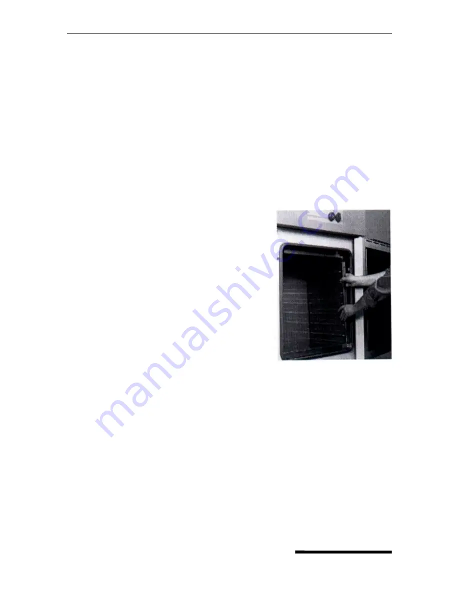
Cleaning must be carried out only after cooling
down of the unit and after disconnecting the cord
from the mains. Clean the inner walls with water
and detergent, eventually with appropriate
chemical stuffs; outer surface of the unit should
be cleaned only with a cloth wetted by water
with detergent. Abrasive agents could cause
scoring of sheets. 

If you wish to clean also the

external chamber jacket, remove the inner
chamber walls in following way:

Shift the upper chamber wall out of the unit,
remove the side walls, bottom and rear wall.

Summary of Contents for CLIMACELL 111

Page 1: ...ine Cooling incubator with controlled humidity CLIMACELL 111 222 404 707 Operating instructions MMM Medcenter GmbH Manufacturer MMM Medcenter Einrichtungen GmbH Schulstrasse 29 D 82 166 Gr felfing Tel...

Page 2: ...elect language 12 4 4 7 Service 06 Setting the switching time of the inner socket optional 12 4 4 8 Service 07 Setting the safety thermostat 12 4 4 9 Service 08 Selecting the water quality 13 4 4 10 S...

Page 3: ...8 4 3 S3 is active temperature is heading towards T2 23 4 8 4 4 S4 is active T2 is reached delay time at T2 is running 23 4 8 5 Information on the set parameters during the device s running 23 4 8 6 S...

Page 4: ...2 digit LCD display illuminated All parameters seen at once To your information the display is already set up to be used in product ranges coming out in future CLIMACELL is manufactured of high grade...

Page 5: ...plosive anaesthetics Every mounting and demounting of the unit s parts may be carried out only after disconnecting the unit from the mains by pulling the supply cord out of the socket Installation of...

Page 6: ...can cause a scald As Climacell is connected to water supply and drain place the unit in a room with its floor sloping towards the drain 2 3 Permitted loads size weight kg tray total weight kg 55 20 5...

Page 7: ...tion system 4 Condenser 15 Boiling vessel for steam generator 5 Compressor coolant R134a 16 Pump 6 Cooling snakelike tubing 6a 6b 17 Drain of waste water 7 Heating bodies in the heating space 18 Input...

Page 8: ...efined above according to DIN 12 880 marked with heavy lines in the picture the light lines mark the inner walls of the chamber It means that over the highest shelf the values of the chapter Technical...

Page 9: ...ines state of temperature regulator cooling active 10 indicator light failure 11 indicator light of safety thermostat shines temperature surpassed the limit set on the safety thermostat heating is off...

Page 10: ...c water treatment placed on the steam generator inlet pipe the treatment suppresses forming of mineral deposits inside the generator Fix one end of the supplied outlet hose to the outlet pipe before w...

Page 11: ...ip card and repeat the procedure Pressing START STOP enter the program storing service at first The choices P1 P4 or P5 or P6 are available Select by pressing To store the program press button In deta...

Page 12: ...livered by the producer Using of another card could cause damaging of your unit s regulator and the guarantee would be cancelled 4 4 4 Service 03 Set the real time and date Pressing START STOP you ent...

Page 13: ...the by you selected lower temperature limit adjustable in the range from 5 C to 39 C at the position 12 13 14 symbols XXX on the display set the upper temperature limit adjustable in the range from 0...

Page 14: ...tion 0 totally off is at display shown as OFF 100 is shown as ON The illumination is constant during the whole time as the segment continues P5 P6 there is possible to set the illumination at steps of...

Page 15: ...4 13 Setting the operating conditions of temperature and relative humidity and their limitations Relation between the operating temperature T C and the operating relative humidity RH in setting the o...

Page 16: ...ue from 00 to 100 in 10 steps of maximum rate and RH between 10 and 90 with limitations given in diagram in paragraph Setting the operating conditions of temperature and relative humidity and their li...

Page 17: ...ther active functions are switched off P 2 The unit operates at the set temperature and RH till the expiration of set time max 99h 59 min 4 6 1 Set P2 With help of buttons put the cursor to the positi...

Page 18: ...he unit operates at the set temperature The duration of the set temperature can be limited or unlimited in time 4 7 1 Setting the program P3 By means of set the cursor to the position Program and come...

Page 19: ...ure and RH negatively 4 7 2 LCD read out shown 4 7 3 Start P3 Press START STOP a sound will appear and the windmill in the first digit of LCD starts running clockwise See the following LCD read out 4...

Page 20: ...d 4 8 1 Set P4 Index T0 initial chamber temperature T1 temperature level 1 T2 temperature level 2 Digit 11 on LCD placed between temperature and dwell time values shows the following information r ram...

Page 21: ...et the ramp at T1 Return the cursor to the digit 11 on LCD and by pressing select r Switch to the position and set the required ramp max value 3 20 C min for T0 T1 If the ramp is not needed leave r on...

Page 22: ...2 and the delay time 4 8 3 4 Set the ramp at T2 Return the cursor to the digit 11 on LCD and by pressing button select r Switch to position and set the required ramp max value 3 20 C min for T1 T2 If...

Page 23: ...perature and relative humidity and their limitations Caution Do not reduce the ventilator rate if not necessary The reduced ventilator rate could influence the regulation of temperature and RH negativ...

Page 24: ...ctive temperature is heading towards T2 C C C actual temperature hr min time running since the end of T1 till it reaches T2 4 8 4 4 S4 is active T2 is reached delay time at T2 is running C C C actual...

Page 25: ...s 1 to 15 can be set as the last and infinite that is the program at this segment must be finished by START STOP button If the cycle selection is active on LCD at the moment of the start see fig Displ...

Page 26: ...he last infinite length D XX X required temperature of the set segment the end temp E tXX XX required length of the set segment deciding is the ramp or TXX XX required length of the set segment decidi...

Page 27: ...peed at the moment G XX disengaged H XXX the light at the moment 4 9 2 Description of P6 and its control The program consists of 16 segments Segment 0 represents delayed start it is determined only by...

Page 28: ...t0 to t15 each of segments up to a year ramp r1 to r15 0 to 3 2 C min for heating 1 0 to 0 C for cooling temperature T1 to T15 0 0 to 99 9 C fan speed V1 to V15 0 to100 with 10 steps relative humidity...

Page 29: ...he time and temperature parameters in the programs 5 and 6 it is suitable to follow the following principles For setting the temperature it is necessary to cancel the ramp of the following segment the...

Page 30: ...tion that this is a sufficiently long time for overcoming from one temperature to the other if it is not the case the pause must be set longer according to results of experiments The printer prints RH...

Page 31: ...the operator The acoustic signal is the same as in case of the hard error the optical signal differs from reporting the hard error by flickering of the appropriate message on the display In case of ha...

Page 32: ...erature in the chamber below eventually temperature on the flexible sensor RH A new head is printed if the cooling incubator is started some parameter has been changed 4 You can stop the printing by s...

Page 33: ...cks in between the chamber and the outer casing To check the seal take a piece of paper and put it between the door and the chamber Pull it out slowly a rather strong resistance should be noticeable T...

Page 34: ...minated surfaces with a suitable and approved disinfecting agent Before using another cleaning or decontamination method with the exception of the by us recommended methods the user should consult the...

Page 35: ...ariation Deviation Heating up time to 37 C from the ambient temperature Cooling down time from 22 C to 10 C Recovery time after 1 min door open from 0 0 C at 10 C at 37 C at 37 C at 50 C to C C C C mi...

Page 36: ...is responsible for safety technical parameters of the unit only if all repairs and adjustments are carried out by producer or another by producer authorised organisation and if the parts used in repa...

Page 37: ...nt flexible sensor is used for measuring of material temperature directly in the chamber The date of temperature on this sensor PT2 is displayed on LCD in the position of time date while these two dat...

Page 38: ...ug must be connected only by a person with a sufficient qualification When the plug is plugged in and out of the socket or when manipulated with the inner equipment CLIMACELL must be switched off the...

Reviews: