background image

Form 801680 

Page Number - 5

static Pressure test (engine off)

For diagnosing:

Cooling system leaks

set-up & Procedure:

1.   Ensure the cooling system is cool and not pressurized. 

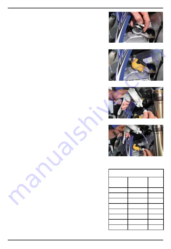
Carefully remove the radiator or coolant bottle pressure cap 

(Fig. 1).

2.   Check to see that the radiator or coolant bottle is filled to 

the proper level, and check hoses for visual damage or 

leaks. Fill and repair as necessary prior to testing.

3.   Apply water or coolant to the rubber gasket of cooling 

system test adapter, and install it in place of the  

pressure cap (Fig. 2).

4.   Secure one end of the clear hose to the pressure pump 

using the compression nut (Fig. 3).

5.   Secure the second end of the hose to the cooling system 

test adapter using the compression nut (Fig. 4).

6.   Note the operating pressure of the cooling system  

indicated on the cap or in the vehicle repair manual.

7.   Operate the pressure pump until the needle on the  

pressure gauge moves to the high end of the colored band 

indicating the appropriate pressure range of the cap (see 

Chart A).


caUtion: Do not pressurize the cooling system beyond 

the appropriate color of band for the system being tested.

8.   Monitor the gauge for at least two minutes. If the pressure 

reading drops, a leak is present.

9.   With the system still pressurized, perform a visual  

inspection of the entire cooling system. Check hoses  

and connections for seepage, which would indicate a leak. 

Return to the gauge and check the reading once more.

10.  Most leaks are external, and visible seepage occurs. 

However, a drop in pressure with no visible leakage can 

indicate a blown head gasket or cracked block, where fluid 

leaks into the combustion chamber. Visually inspect oil 

and transmission fluid for signs of coolant. Proceed to the 

Dynamic Pressure Test for better methods of diagnosing 

internal leaks.

11.  When testing is complete, release the pressure in the 

system by pressing the pressure relief valve located on the 

pump hose near the quick-connect couple.

12.  Repair leaks if necessary, and retest.
13.  Disconnect components, clean and store them properly.
14.  Refill the radiator or coolant bottle to the proper level, and 

replace the cap.

Fig. 1

Fig. 2

Fig. 3

Fig. 4

chart a:  

cooling system cap Pressure test ranges

Rated  

Pressure (PSI)

Pressure Range 

(PSI)

Arrow/Band 

Color

4

3 - 5

Yellow

7

6 - 8

Green

10

9 - 11

White

13 or 14

12 - 16

Blue

15 or 16

14 - 18

Yellow

18

16 - 20

Black

20

18 - 22

Green

30

28 - 30

Red

Summary of Contents for MV4510

Page 1: ...service parts To order replacement or service parts visit us online at www mityvacparts com or call toll free 1 800 992 9898 Europe Africa Heinrich Hertz Str 2 8 D 69183 Walldorf Germany Phone 49 622...

Page 2: ...Form 801680 Table of Contents Service Parts Accessories 3 Applications and Basics of Testing 4 Static Pressure Test Engine Off 5 Dynamic Pressure Test Engine On 6 Cap Pressure Test 7 Spanish 8 French...

Page 3: ...4 Piston Rod Seal 1 5 Cross Pin 1 6 Piston Spring 1 7 Piston 1 8 Piston Seal 1 9 O ring 1 10 Manifold 1 11 Schrader Valve 1 1 12 Compression Nut 1 2 13 Lever 1 14 E clip 1 15 Lever Pin 1 16 Gauge 1 Sc...

Page 4: ...the pressure Internal leaks which may not be visible typically indicate a blown head gasket or damaged block or head and can be diagnosed by monitoring the pressure during a quick engine on test When...

Page 5: ...of band for the system being tested 8 Monitor the gauge for at least two minutes If the pressure reading drops a leak is present 9 With the system still pressurized perform a visual inspection of the...

Page 6: ...pressing the pressure relief lever located on pump Disconnect the test equipment and replace the head gasket If no immediate or rapid pressure buildup is indicated operate the pressure pump to bring t...

Page 7: ...lant to the rubber gasket and or o ring on the cap and assemble the cap to the cap adapter Fig 10 3 Secure one end of the clear hose to the pressure pump using the compression nut Fig 11 4 Secure the...

Page 8: ...trucciones de uso del producto Necesita piezas de servicio Para pedir piezas de repuesto o servicio vis tenos en l nea en www mityvacparts com o llame al tel fono gratuito 1 800 992 9898 Europa frica...

Page 9: ...p gina 9 ndice Piezas de servicio y accesorios 10 Aplicaciones y fundamentos de las pruebas 11 Prueba de presi n est tica motor apagado 12 Prueba de presi n din mica motor encendido 13 Prueba de pres...

Page 10: ...n 1 7 Pist n 1 8 Sello de pist n 1 9 Junta t rica 1 10 M ltiple 1 11 V lvula Schrader 1 1 12 Tuerca de compresi n 1 2 13 Palanca 1 14 Presilla en E 1 15 Pasador de palanca 1 16 Man metro 1 Herramienta...

Page 11: ...visibles indican normalmente una empaquetadura de cabeza reventada o un bloque o cabeza da ados y pueden diagnosti carse supervisando la presi n durante una prueba r pida con el motor en marcha Al de...

Page 12: ...a el sistema que se est sometiendo a prueba 8 Supervise el man metro durante al menos dos minutos Si desciende la lectura de presi n quiere decir que hay una fuga presente 9 Con el sistema todav a som...

Page 13: ...o es una indicaci n de una rotura entre un cilindro y el sistema de enfriamiento debida con gran probabilidad a una empa quetadura de culata reventada Apague Inmediatamente el motor y alivie la presi...

Page 14: ...efrigerante Fig 9 2 Aplique agua o refrigerante a la empaquetadura de goma de la tapa y monte la tapa en el adaptador de la tapa Fig 10 3 Fije un extremo de la manguera transparente en la bomba de pre...

Page 15: ...s d utilisation de nos produits Pour toute pi ce de rechange Pour commander des pi ces de rechange nous rendre visite en ligne www mityvacparts com ou nous appeler sans frais au 1 800 992 9898 Europe...

Page 16: ...des mati res Pi ces de rechange et accessoires 17 Applications et principes de base du contr le 18 Essai de pression statique moteur arr t 19 Essai de pression dynamique moteur en marche 20 Essai de...

Page 17: ...ntre goupille 1 6 Ressort de piston 1 7 Piston 1 8 Joint de piston 1 9 Joint torique 1 10 Tubulure 1 11 Vanne Schrader 1 1 12 crou de serrage 1 2 13 Levier 1 14 Attache en E 1 15 Axe de levier 1 16 Ma...

Page 18: ...ment par un joint de culasse saut ou par un bloc ou une culasse endommag et peu vent tre diagnostiqu es en surveillant la pression pendant un test rapide avec le moteur en marche Pour d cider o tablir...

Page 19: ...de refroidisse ment au del de la couleur de la bande correspondant au syst me contr ler 8 Surveillez le manom tre pendant au moins deux minutes Si la pression indiqu e baisse il y a une fuite 9 Avec l...

Page 20: ...urveillez le manom tre Une mont e en pression imm diate et rapide indique une br che entre un cylindre et le syst me de refroidissement due tr s vraisemblablement un claquage du joint de culasse Arr t...

Page 21: ...roidissement Fig 9 2 Mouillez le joint en caoutchouc et ou le joint torique du bouchon avec de l eau ou du liquide de refroidissement et joignez le bouchon l adaptateur Fig 10 3 Fixez une des extr mit...

Page 22: ...TE OU TACITE Y COMPRIS ENTRE AUTRES CELLES DE QUALIT MARCH ANDE ET D ADAPTATION UN USAGE PARTICULIER Lincoln ne sera en aucun cas responsable de dommages accessoires ou indirects La responsabilit de L...

Reviews: