18 - 1
18.1 Error Contents Display
18. ERROR MESSAGE AND SYSTEM
ALARM
This chapter describes the error messages and system alarm displayed in the GOT.
As the error code and error message displaying functions when an error occurs at the GOT or Controller, the
system alarm is available.
The error code can also be confirmed in the error code storage area of the system information.
For details of system alarm and system information, refer to the following.
GT Designer2 Version Screen Design Manual
18.1 Error Contents Display
This section describes how to identify the error code and system alarm displayed on the monitor screen by
the system alarm display function and the reference material.
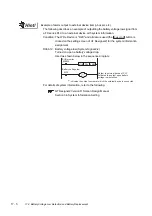
(1) Displaying format on monitor screen ... Displayed in user setting position
The system alarm is displayed together with an error code, its error message and occurrence time.
The displayed error code and error message are registered to the GOT in advance and need not to
be prepared by the user.
Display priority
The alarm is displayed in the following priority if the displaying range is one or two lines.
(1) GOT error
:The error in the GOT is displayed as an alarm.
(2) CPU error
:The error in the PLC CPU is displayed as an alarm.
(3) Network error
:The error in the network is displayed as an alarm.
Alarms with smaller priority cannot be displayed if system alarms overflow the displaying range.
As well, the error code, error message or time is not displayed if the displayed message overflows
each line in the displaying range.
335 Memory card battery voltage low. Replace battery. 16:40:30
104 Parameter error
400 Unable to communicate with CPU.
Error code
Error message
Time of occurrence
(Displayed only for errors related to GOT.)
Up to 3 lines are displayed.
(1 line per error)
Summary of Contents for GOT1000 GT11
Page 1: ......
Page 2: ......
Page 251: ...Index 2 U Utility function list 9 2 W Wiring 7 1...
Page 252: ...Index 3 MEMO...
Page 255: ......
Page 256: ......

