background image

11 - 1

9

UTILIT

Y

 FUNCTION

10

C

O

MMUNICA

TION 

INT

E

RF

A

C

SETTI

NG

11

DISP

LA

Y AND 

OPE

R

A

T

IO

SETTIN

G

S

12

CLOCK

 SE

T

T

IN

GS


AND  

BA

TTER

Y


ST

A

T

US

 DI

SPL

A

Y

13

FIL

E

 D

ISP

LA

Y AND 

COP

Y

14

G

O

T SE

L

F

 C

H

EC

K

15

CLE

A

NING OF 

DISPL

A

Y

 S

E

CTION

16

IN

ST

AL

LA

TI

ON

 O

BOO

TOS

 AN

D


ST

ANDA

RD MONI

TO

R O

S

11.1  Display Settings

11.1.1  Display setting functions

11. DISPLAY AND OPERATION 

SETTINGS (GOT SET UP)

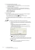
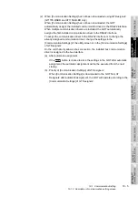
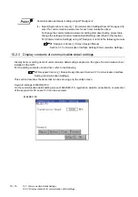
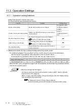
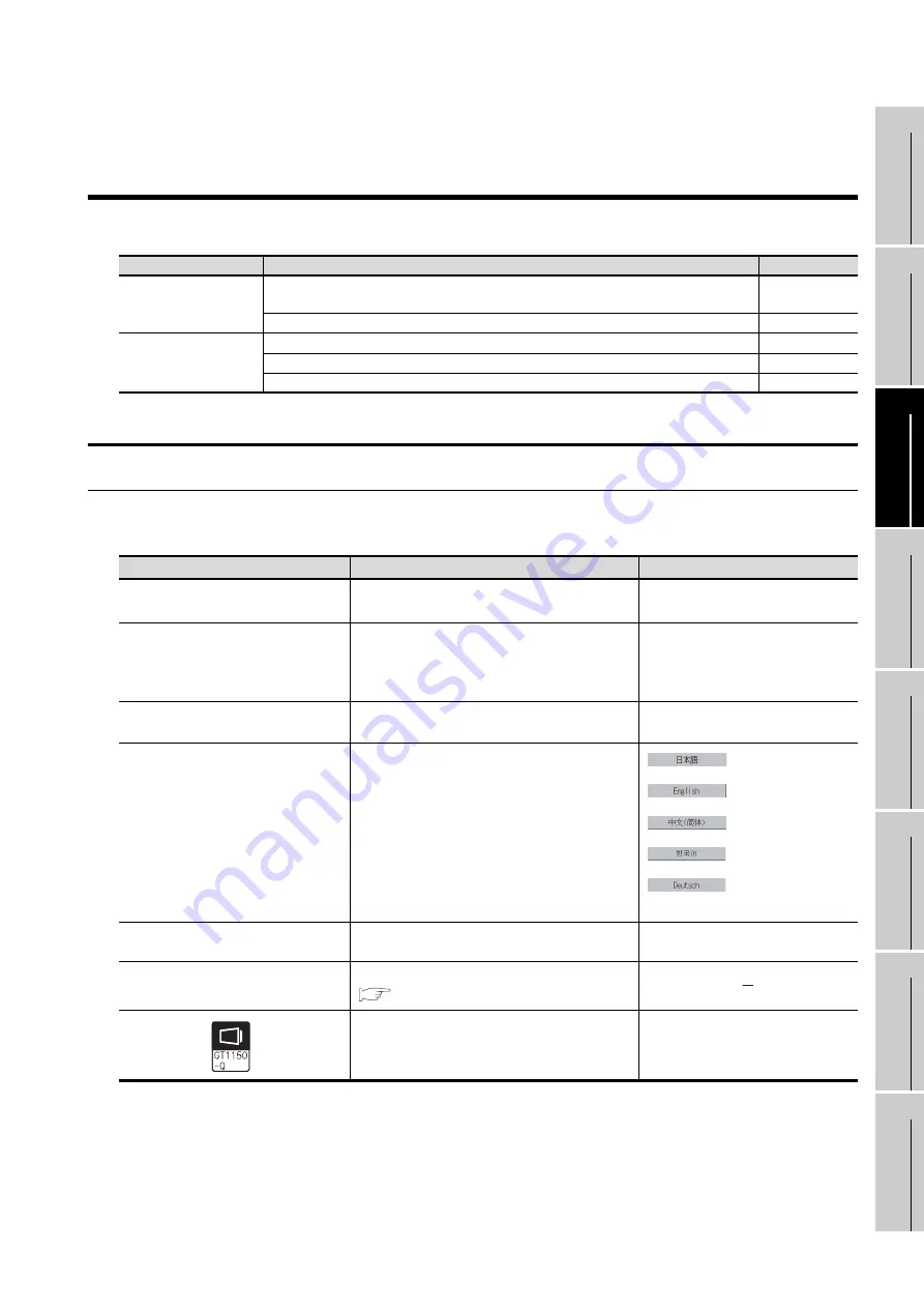
Setting screen for display and setting screen for operation can be displayed from GOT setup.
In the setting screen for display and the setting screen for operation, the following settings can be set.

11.1 Display Settings

11.1.1 Display setting functions

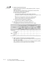
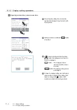
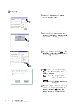
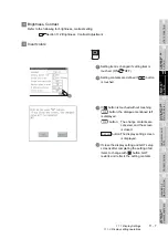
Setting regarding display is possible.
The items which can be set are shown below. 

*1

If setting 0, the title screen is not hidden.
The title screen is always displayed for 4 seconds or longer (which changes depending on the project data 
contents).

*2

Applicated to GT1150-QLBD only.(Standard monitor OS Ver.03.01.00 or later) 
                                                      (BootOS Ver.03.01.**.M or later)

Screen

Description

Reference page

Setting screen for display

Opening screen time, screen save time, screen save backlight, language, 

battery alarm display, 

invert colors

11-1

Brightness, contrast

11-8

Setting screen for 
operation

Buzzer volume, window move buzzer

11-12

Security setting

11-12

Utility call key

11-12

Items

Contents

Setting range

Opening screen time

The title display period at the main unit boot can be 
set.

0 to 60 seconds 

*1

<At factory shipment: 5 seconds >

Screen save time

The period from the user stops the touch panel 
operation till the screen save function starts can be 
set.

0 to 60 minutes
<At factory shipment: 0 minutes>
When set to 0, the function becomes 
invalid.

Screen save backlight

Whether turn ON or OFF the backlight simultaneously 
at the screen save function start can be specified.

ON/OFF
<At factory shipment: OFF>

Language

Confirmation of the current language and switching 
language can be performed regarding with the 
language displayed by utility and dialogue.


Japanese


English


Chinese (Simplified)


Korean


German

Factory setting: User-selected language

Battery alarm display

Whether to display system alarm when the voltage of the
GOT internal battery has dropped can be specified.

<At factory shipment: OFF>

Brightness, Contrast

The brightness or contrast can be adjusted.

Section 11.2 Brightness, Contrast Adjustment

Invert colors 

*2


User creation screen and utility screen can be set to 
be highlighted or not.

ON/OFF
<At factory shipment: OFF>

Summary of Contents for GOT1000 GT11

Page 1: ......

Page 2: ......

Page 3: ...ident due to false output or malfunction If a communication error including cable disconnection occurs while monitoring on the GOT communication between the GOT and PLC CPU is suspended and the GOT be...

Page 4: ...e monitor screen appears blank CAUTION Do not bundle the control and communication cables with main circuit power or other wiring Run the above cables separately from such wiring and keep them a minim...

Page 5: ...ion due to poor contact When removing a CF card from the GOT make sure to support the CF card by hand as it may pop out Failure to do so may cause the CF card to drop from the GOT and break DANGER Be...

Page 6: ...r or counter and changing the buffer memory current value read through the manual carefully and make yourself familiar with the operation method During test operation never change the data of the devi...

Page 7: ...fore touching the unit always touch grounded metal etc to discharge static electricity from human body etc Not doing so can cause the unit to fail or malfunction CAUTION When disposing of the product...

Page 8: ...ENERIC TERMS IN THIS MANUAL Section 2 2 7 1 9 2 9 3 10 1 Chapter 11 Section 13 1 Chapter 14 Section 16 3 16 4 Appendix1 Appendix2 Appendix 4 Additions Section 7 2 13 7 14 8 14 9 May 2007 JY997D17501 D...

Page 9: ...ses the product associated with this manual This product has been manufactured as a general purpose part for general industries and has not been designed or manufactured to be incorporated in a device...

Page 10: ...s 3 1 3 2 Performance Specifications 3 2 3 3 Built in Interface Specifications 3 5 3 4 Power Supply Specifications 3 6 4 PART NAME 4 1 4 1 Front Panel 4 1 4 2 Back Panel 4 2 5 EMC DIRECTIVE 5 1 5 1 Re...

Page 11: ...tor 8 4 8 2 1 Applicable memory card adaptor 8 4 8 2 2 Installing procedure of the CF card into a memory card adaptor 8 4 8 3 Option Function Board 8 5 8 3 1 Applicable option function board 8 5 8 3 2...

Page 12: ...s contrast adjustment function 11 8 11 2 2 Display operation of brightness contrast 11 8 11 2 3 Brightness adjustment operation 11 9 11 3 Operation Settings 11 10 11 3 1 Operation setting functions 11...

Page 13: ...d 13 31 13 6 Memory Information 13 32 13 6 1 Memory information function 13 32 13 6 2 Memory information display operation 13 32 13 6 3 Display example of memory information 13 33 13 7 GOT data packag...

Page 14: ...ation 16 2 16 2 Prior Preparations for Installing BootOS and Standard Monitor OS 16 3 16 3 BootOS and Standard Monitor OS Installation Using CF Card 16 4 16 3 1 Installation method when the GOT is tur...

Page 15: ...ES App 1 Appendix 1 External Dimensions App 1 Appendix 2 Usage Condition of Utility Function App 8 Appendix 3 Transportation Precautions App 14 Appendix 3 1 Relevant models App 14 Appendix 3 2 Transpo...

Page 16: ...s Sold separately 1 SH 080529ENG 1D7M24 GT Designer2 Version2 Screen Design Manual For GOT1000 Series 1 3 GT Designer2 Version2 Screen Design Manual For GOT1000 Series 2 3 GT Designer2 Version2 Screen...

Page 17: ...GT1585 GT157 GT156 GT155 GT115 GT1155 Q Abbreviation of GT1155 QTBDQ GT1155 QSBDQ GT1155 QTBDA GT1155 QSBDA GT1155 QSBD GT1150 Q Abbreviation of GT1150 QLBDQ GT1150 QLBDA GT1150 QLBD Handy GOT GT1155H...

Page 18: ...0PSGB GT11 50PSCW GT11 50PSGW GT11H 50PSC GT10 30PSCB GT10 30PSGB GT10 30PSCW GT10 30PSGW GT10 20PSCB GT10 20PSGB GT10 20PSCW GT10 20PSGW USB environmental protection cover GT15 UCOV GT11 50UCOV Stand...

Page 19: ...bbreviation of PLC manufactured by YASKAWA Electric Corporation Yokogawa PLC Abbreviation of PLC manufactured by Yokogawa Electric Corporation Allen Bradley PLC Abbreviation of PLC manufactured by All...

Page 20: ...on Carries out write read check of memory When drive is not displayed When the drive memory to check is not displayed confirm the mounting procedure or memory type with reference to the following CF c...

Page 21: ...can be arditrarily arranged on the display A horizontal format or vertical format may be selected for displaying a user s project Moreover multiple screens created within GT Designer2 can be individu...

Page 22: ...ansferring data to GOT refer to the following manuals 1 Stored in the GT Works 2 GT Designer2 in PDF format Purpose GT Designer2 Version Basic Operation Data Transfer Manual 1 GT Designer2 Version Scr...

Page 23: ...A b GOT1000 Series Gateway Functions Manual Describes how to use the gateway function c GT Simulator 2 Version Operation Manual Describes how to simulate the created project data with GT Simulator2 d...

Page 24: ...high speed touch switch response 2 More efficient GOT operations including screen design startup adjustment management and maintenance works The 3MB user memory is included as standard CF card interfa...

Page 25: ...d monitor OS communication driver extended functions OS option OS to GOT 2 Download the project data created by the PC Write the OS project data installed in the PC in the CF card 1 Write the standard...

Page 26: ...s applicable to GOT1000 series and cable refer to the following GOT1000 Series Connection Manual GT11 does not connect a printer Bar code reader Commercially available Option function board CF card GO...

Page 27: ...C L 5VDC T TFT color High intensity wide angle view N TFT color S STN color L STN monochrome GOT 1000 series GT15 GT11 GT10 Panel color type Screen size type Display color type Resolution Power type D...

Page 28: ...l interface GT1155 QTBDA 5 7 320 x 240 dots TFT color liquid crystal 256 colors 24VDC memory size 3MB built in battery built in A bus serial interface GT1155 QSBDQ 5 7 320 x 240 dots STN color liquid...

Page 29: ...D sub 25 pins and GOT For connecting FA CNV CBL and GOT For connecting serial communication unit AJ71QC24 N R4 and GOT GT01 C100R4 25P 10m GT01 C200R4 25P 20m GT01 C300R4 25P 30m Computer link connec...

Page 30: ...length 3m GT15 A1SC50B Cable length 5m For connecting QnAS AnSCPU and GOT GT15 A1SC05NB Cable length 0 45m For connecting QnAS AnSCPU motion controller CPU A series and A7GT CNB GT15 A1SC07NB Cable l...

Page 31: ...gth 10m GT09 C200R40101 9P Cable length 20m GT09 C300R40101 9P Cable length 30m GT09 C30R40102 9P Cable length 3m For connecting GOT to OMRON rack type host link unit communication board GT09 C100R401...

Page 32: ...C300R40602 15P Cable length 30m GT09 C30R40603 6T Cable length 3m For connecting GOT to SHARP link unit GT09 C100R40603 6T Cable length 10m GT09 C200R40603 6T Cable length 20m GT09 C300R40603 6T Cabl...

Page 33: ...connecting GOT to MATSUSHITA RS422 232C conversion adapter GT09 C30R20902 9P Cable length 3m For connecting GOT to the tool port or RS232C port of MATSUSHITA PLC computer communication unit GT09 C30R...

Page 34: ...nk module GT09 C100R40301 6T Cable length 10m GT09 C200R40301 6T Cable length 20m GT09 C300R40301 6T Cable length 30m GT09 C30R40302 6T Cable length 3m GT09 C100R40302 6T Cable length 10m GT09 C200R40...

Page 35: ...e Model name Contents Stand GT05 50STAND Stand for 5 7 A9GT 50STAND Stand Common to A95 GOT Product name Model name Contents Battery 4 GT11 50BAT For storing clock data alarm history and recipe data P...

Page 36: ...r Mitsubishi industrial automation products MELFANSweb home page MELFANSweb home page http wwwf2 mitsubishielectric co jp melfansweb english index_e htm Product name Model name Contents GT Designer2 S...

Page 37: ...ion degree 2 only non conductive pollution occurs but temporary conductivity may be produced due to condensation Item Specifications Operating ambient temperature Display section 0 to 50 Other than di...

Page 38: ...ity of LCD only 350 cd m2 Adjustable in 8 levels 220 cd m2 Adjustable in 8 levels Intensity adjustment 8 level adjustment Life 2 Approx 50 000h Time for display intensity to become 1 5 at operating am...

Page 39: ...Intensity adjustment 8 level adjustment Life 2 Approx 50 000 h at operating ambient temperature of 25 Backlight Cold cathode fluorescent tube irreplaceable by the user backlight detection function is...

Page 40: ...n the displayscreen and increases the backlight life 3 ROM in which new data can be written without deleting the written data 4 Compliant with IP67 when the USB environmental protection cover is attac...

Page 41: ...ion transparent function USB Serial interface USB compliant Full Speed 12Mbps device 1ch Use PC communication project data upload download OS installation transparent function CF card PCMCIA compliant...

Page 42: ...or less 26 4V 2ms Permissible instantaneous power failure time Within 5ms Noise immunity Noise voltage 1000Vp p Noise width 1 s by noise simulator of 30 to 100Hz noise frequency Dielectric withstand v...

Page 43: ...t power supply voltage DC24V 10 15 ripple voltage 200mV or less Fuse built in irreplaceable 1 0A Power consumption 9 84W 410mA 24VDC or less 9 84W 410mA 24VDC or less 9 84W 410mA 24VDC or less With ba...

Page 44: ...or operating the touch switches in the utility screen and the user creation screen 3 USB interface USB interface for connecting a personal computer OS installation project data download transparent 4...

Page 45: ...ng access to CF card before removing the CF card from the GOT ON CF card being accessed CF card removal prohibited OFF No access to CF card CF card removal possible 7 CF card cover Open or close when...

Page 46: ...Rating plate nameplate 5 CF card access LED Lit CF card accessed Not lit CF card not accessed 6 CF card access switch Switch for prohibiting access to CF card before removing the CF card from the GOT...

Page 47: ...n conformance to the EMC Directive of the machinery constructed using the GOT The details of these precautions has been prepared based on the requirements and the applicable standards control However...

Page 48: ...ed as described below a Provide an earthing point near the GOT Earth the power supply s FG terminal FG Frame Ground with the thickest and shortest wire possible The wire length must be 30cm 11 18inch...

Page 49: ...due to the accumulated dust An environment for a typical factory floor Pollution level 4 Continuous conductivity may occur due to rain snow etc An outdoor environment 5 1 3 Grounding It is necessary...

Page 50: ...ts rating plate Products that the EMC Directive applies to are marked with the CE mark logo 5 2 2 Connection format Connection conditions where the GT11 is applicable to the EMC Directive are shown be...

Page 51: ...ower wire and ground wire The GT1155 QSBD and GT1150 QLBD unit requires an additional ferrite filter to be attached to the 24V DC power supply cables The filter should be attached in a similar manner...

Page 52: ...n this manual Not doing so can cause an electric shock fire malfunction or product damage or deterioration When mounting the GOT to the control panel tighten the mounting screws in the specified torqu...

Page 53: ...he GOT requires a space with the same dimensions as the horizontal installation turned 90 degrees clockwise seen from the display side Applicable cable Some cables may need to be longer than the speci...

Page 54: ...1155 QSBDQ GT1150 QLBDQ GT1155 QTBDA GT1155 QSBDA GT1150 QLBDA No Name 1 Bus cable 2 PC cable barcode cable 152 5 99 120 4 73 140 5 52 A B 1 2 Unit mm inch Type A B GT1155 QTBDQ GT1155 QSBDQ GT1150 QL...

Page 55: ...al installation The same clearances must be maintained when rotating the GOT 90 degrees clockwise for a vertical installation Installation Environment A D B C E When the CF card is not used When the C...

Page 56: ...l have a longer lifetime if used within the mounting angles shown above Ideally the temperature inside the control panel should not exceed 0 to 40 2 Vertical installation When the temperature inside t...

Page 57: ...SBD and GT1150 QLBD Install packing to the packing installation groove on the back panel of the GOT While referring to the cross sectional view of the packing shown right push the thinner side into th...

Page 58: ...he panel and make a surface waviness on the protective sheet GT1155 QSBD GT1150 QLBD GT1155 QTBDQ GT1155 QTBDA GT1155 QSBDQ GT1155 QSBDA GT1150 QLBDQ GT1150 QLBDA 4 A protection film is attached on th...

Page 59: ...t the ground cable to the ground b Use a short and thick cable to lower its impedance c Ground the power system and the control system separately WIRING PRECAUTIONS DANGER Be sure to shut off all phas...

Page 60: ...drop and tighten the terminal screw with the specified torque securely 1 GT1155 QSBD GT1150 QLBD 2 GT1155 QTBDQ GT1155 QSBDQ GT1150 QLBDQ GT1155 QTBDA GT1155 QSBDA GT1150 QLBDA 24VDC power supply CF C...

Page 61: ...GOT s ground cable and power line together can cause interference noise which may result in malfunctions Keeping the GOT s ground cable and power line away from each other will help minimize noise in...

Page 62: ...ses such piece of control equipment as a sequencer to the panel to which the GOT is grounded the ground cable may have to be directly connected to the terminal on the GOT If electric potential differe...

Page 63: ...aken Wind the wire around the ferrite core several times approx 3 times if a ferrite core is used If the wiring method as shown in Remedy 2 1 is not feasible follow Remedy 2 2 Panel grounding Remedy 1...

Page 64: ...of the panel make two pullout holes away from each other and pull the cables through Putting both cables through the same pullout hole will increase noise interference Keep the power line and communic...

Page 65: ...motors surge noise interference is suspected If this problem happens keep the ground cable and communication cable away from the load If that is not possible an installation of a surge killer will hel...

Page 66: ...provide the same grounding as described in the section 1 above to both GOTs 1 Ground the FG terminal of the power supply terminal block on the GOT 2 FG wires on GT15 C BS must be 28 cm or less 3 Leave...

Page 67: ...tory function Refer to the following for details Chapter 13 FILE DISPLAY AND COPY PROGRAM DATA CONTROL 8 1 1 Applicable CF card The following CF cards are applicable for GT15 The flash PC card of the...

Page 68: ...ff When the CF card access LED turns off the CF card can be installed even during the GOT power on 2 To install the CF card to the GOT insert the CF card into the CF card interface with its front side...

Page 69: ...ring the GOT power on 2 Push in the CF card eject button of the GOT to eject the CF card and then remove the CF card Precautions for removing the CF card 1 While the CF card access LED is on do not in...

Page 70: ...data on the CF card from the PC or load alarm history data from the CF card to the PC Refer to the following for the details related to CF card Section 8 1 CF Card 8 2 1 Applicable memory card adaptor...

Page 71: ...the hardware version with the products rating plate 2 GT1155 QTBDQ GT1155 QTBDA GT1155 QSBDQ GT1155 QSBDA GT1150 QLBDQ GT1150 QLBDA The above models of GOTs have built in option functions and do not...

Page 72: ...ion function board connector on the back panel of the GOT Push down the option function board by approximately 0 5mm with fingers along the groove for reverse installation protection Do not keep the o...

Page 73: ...function board with a fingernail as shown in the figure on the right 3 Pinch the lever with fingers and pull up it vertically to remove the option function board Precautions for installing removing th...

Page 74: ...onnector and insert the new battery connector within 30s 5 Insert the new battery into the holder and close the back cover 6 Turn the GOT power on 7 Check if the battery condition is normal with the u...

Page 75: ...ement The battery is susceptible to natural discharge Order one when necessary GT11 50BAT LOT 54 Connector Year example 2005 last digit L OT 5 4 Model name Month example Apr 1 Jan to 9 Sep X Oct Y Nov...

Page 76: ...d to the GOT remove it too 2 Peel the release paper from the back of the new protective sheet and attach its adhesive side to the GOT display section When attaching the protective sheet make sure to f...

Page 77: ...cted 3 Open the USB environmental protection cover equipped with the GOT and remove the mounting screws 4 Remove the old USB environmental protection cover from the GOT to replace it with the new USB...

Page 78: ...e adjusting fitting of the stand 2 Put the GOT into the stand from the stand front side and fix it using the fixtures For how to mount the GOT refer to the following Section 6 5 Installation Procedure...

Page 79: ...lash memory There are following three types for the installing Standard monitor OS methods Refer to the following for the installation which uses GT Designer2 GT Designer2 Version Basic Operation Data...

Page 80: ...status reactivate When FX series PLC is connected GOT setup Display Setting of opening screen time Setting of screen saving time Setting of screen saving back light ON OFF Switching message language J...

Page 81: ...ersion and screen title Data check of project file Alarm information Deleting alarm log file Copying alarm log file Memory card format Formatting of CF card and Internal SRAM Memory information Displa...

Page 82: ...ed from the GOT utility are displayed Touching a menu item in the main menu will display the setting screen or following selection screen for the item 2 System message switch button This button switch...

Page 83: ...switched to the selected one 1 Only selectable languages are displayed The selectable languages differ depending on the fonts installed in the GOT For details of the fonts refer to the following manu...

Page 84: ...l key can be set by the GOT utility or GT Designer2 At factory shipment the GOT is set to Simultaneous 2 point presses on GOT screen upper right and upper left corners 3 When touching special function...

Page 85: ...The password setting option in GT Designer2 is located in the common menu When the password is not matched the following error message is displayed When touching the screen returns to the monitor scr...

Page 86: ...itted and is displayed at the section 2 Close Return button When a middle screen of the layers is displayed if the Close return button in the right corner of screen is touched returns to the previous...

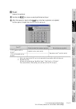
Page 87: ...of the screen when touched In the above mentioned screen example there is no setting item which displays the keyboard For the operation of keyboard refer to the next page Touching confirms the numeri...

Page 88: ...on which will not interrupt the inputting 3 Input numeric with keyboard to Key Input the numeric Key Touching the key completes numeric input and closes the keyboard Key Touching the key cancels numer...

Page 89: ...ation channel communication driver names display and channel numbers are set Moreover in Communication Detail setting the communication interface details are set Communication parameters setting 10 1...

Page 90: ...on driver assigned to the channel can be changed using the communication setting To change the communication driver it is required to pre install the communication driver to be changed in the GOT Sect...

Page 91: ...OS b GT1155 QTBDQ GT1155 QSBDQ GT1150 QLBDQ GT1155 QTBDA GT1155 QSBDA GT1150 QLBDA Standard interfaces have the following three types BUS For communication with PLC RS232 For communication with PC GT...

Page 92: ...not installed Section 13 2 OS Information 0 is set in the channel number specification menu BOX When setting the channel number to 9 the communication driver Host PC is automatically assigned Precaut...

Page 93: ...matically assigns the first installed communication driver to the RS422 interface To assign the communication driver to the RS 232 interface or to change the already assigned communication driver chan...

Page 94: ...ting the GOT After Communication Setting is executed the GOT automatically restarts If the project data is downloaded GOT starts monitoring the communication device after restarting Before starting th...

Page 95: ...ultiple communication drivers cannot be used at the same time Multi channel function cannot be used 2 Display of communication driver Communication drivers are displayed in the order of installation T...

Page 96: ...displayed 3 Enter the channel number from the keyboard and touch the key to settle the entered value Setting the channel number to 1 displays the name of the communication driver for which CH No 1 is...

Page 97: ...the Communication Detail setting screen Set communication parameters from this screen Refer to the following for the setting change operation Section 9 3 3 Basic operation of settings change Function...

Page 98: ...2 Version Screen Design Manual Section 3 7 Communication Interface Setting Communication Settings 10 2 3 Display contents of communication detail settings Display items or setting items of communicat...

Page 99: ...s input and the key is touched registration is completed For the keyword 8 digits from 0 to 9 or A to F must be set 1 Refer to the manual for the PLC in use for the models that are compatible with the...

Page 100: ...ord are registered Protection level is selected by Registration options 2 Applicability of monitoring for each keyword protection level The applicability of monitoring for each protection level is as...

Page 101: ...OF BOOTOS AND STANDARD MONITOR OS 2 Delete Registered keyword is deleted 1 Touching the key pops up a keyboard for keyword input 2 When the correct keyword is input and the key is touched the keyword...

Page 102: ...led 1 Refer to the manual for the PLC in use for the models that are compatible with the 2nd keyword 4 Protect A keyword with cancelled protection is reactivated for protection Keyword protection func...

Page 103: ...play invert colors 11 1 Brightness contrast 11 8 Setting screen for operation Buzzer volume window move buzzer 11 12 Security setting 11 12 Utility call key 11 12 Items Contents Setting range Opening...

Page 104: ...setting by Display screen of the GOT GT Designer2 Version Screen Design Manual Section 3 8 Setting of the GOT display and operation GOT setup 2 Screen save and screen save backlight OFF function When...

Page 105: ...ng Restart after setting change If return the display to the GOT setup screen by touching the button after the setting of each item is changed and touch the button on the GOT setup screen the GOT will...

Page 106: ...etting contents are defined if button is touched 3 If button is touched without touching button the dialogue box shown on the left is displayed button The changed value is canceled and the screen is c...

Page 107: ...ave backlight Battery alarm display 1 Setting item is changed if setting item is touched ON OFF 2 Setting contents are defined if button is touched 3 If button is touched without touching button the d...

Page 108: ...are defined if button is touched The language display does not change till is carried out 4 If button is touched without touching button the dialogue box shown on the left is displayed button The chan...

Page 109: ...ness contrast setting Section 11 2 Brightness Contrast Adjustment 5 Invert colors 1 Setting item is changed if setting item is touched ON OFF 2 Setting contents are defined if button is touched 3 If b...

Page 110: ...11 2 2 Display operation of brightness contrast Function Contents Brightness setting Brightness of display part can be adjusted by 8 levels Contrast setting Contrast of display part can be adjusted b...

Page 111: ...ightness can be adjusted by touching key of brightness adjustment 2 Contrast can be adjusted by touching key of contrast adjustment 3 Setting contents are defined if button is touched 4 If button is t...

Page 112: ...tup in System Environment of GT Designer2 When change a part of the setting change the setting by the GOT display setting after downloading the project data GT Designer2 Version Screen Design Manual S...

Page 113: ...er setting change If return the display to the GOT setup screen by touching the button after the setting of each item excluding the security setting is changed and touch the button on the GOT setup sc...

Page 114: ...y Setting 1 Setting items are changed if setting item is touched 2 Setting contents are defined if button is touched 3 If button is touched without touching button the dialogue box shown on the left i...

Page 115: ...OF DISPLAY SECTION 16 INSTALLATION OF BOOTOS AND STANDARD MONITOR OS 11 3 Operation Settings 11 3 3 Setting operation of operation 4 Key sensitivity setting 1 The keyboard is displayed if setting ite...

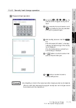
Page 116: ...n 5 8 Security function Password setting GT Designer2 Version Screen Design Manual Section 3 5 Set Password Restrictions on screen display The security level change screen cannot be displayed when pro...

Page 117: ...l temporarily When use GOT after temporarily changing the security level do not forget to return the security level to the original level 1 By touching to to key the password of the changed security l...

Page 118: ...e set For default setting the upper left and upper right corners are specified Operation settings by GT Designer2 Set the utility call key at GOT set up in System Environment of GT Designer2 When chan...

Page 119: ...sition to 2 When the key position is specified by one point the time to switch to the utility when the key position is kept pressing can be set Touch the time area 3 The keyboard is displayed if the i...

Page 120: ...when there are two Make the setting after changing either one of the key positions from to Three of cannot be set at the same time Change the upper right to Change the lower left to Example When chang...

Page 121: ...voltage status of the built in battery is also displayed 12 1 Time Setting and Display 12 1 1 Time setting and display functions Time settings and displaying of the status of GOT built in battery are...

Page 122: ...GT Designer2 GT Designer2 Version Screen Design Manual Section 2 5 Clock Function Adjust Broadcast Adjust and Broadcast can be used appropriately Same as setting in GOT setup in System Environment of...

Page 123: ...n the clock data will not be adjusted Refer to the following for the list of PLC installed with clock function GT Designer2 Version Screen Design Manual Section 2 4 3 PLC CPUs with clock function 2 Cl...

Page 124: ...tically according to the input date Key Contents to Key Input numeric value in cursor position Key Move the cursor Key Move the cursor to the left by one character when Key is touched while inputting...

Page 125: ...immediately Refer to the following for battery replacement procedure Section 8 4 Battery 3 Touching the button reflects the settings and restarts updating the clock display Then the settings are refl...

Page 126: ...llocated 13 1 2 Data type and storage location 1 At system startup The data storage location and transferring write read route for each data type are shown below Drive name Allocation A drive Built in...

Page 127: ...ted when OS or project data is transferred to the memory card Do not delete or edit these folders and files since the GOT uses them If the folders or files are deleted or edited the GOT will not funct...

Page 128: ...monitor OS communication driver or Option OS has already been installed the version information of the OS which has been installed and the dialog for selecting continue not continue will be displayed...

Page 129: ...plate Confirm the version of BootOS installed in the GOT at product shipment by rating plate of GOT rear face a GT1155 QSBD GT1150 QLBD b GT1155 QTBDQ GT1155 QTBDA GT1155 QSBDQ GT1155 QSBDA GT1150 QLB...

Page 130: ...Drive name folder name BootOS OS information screen Built in flash memory C G1BOOT 3 Standard monitor OS Standard monitor OS system screen data Built in flash memory C G1SYS 3 Standard monitor OS sys...

Page 131: ...of the files are also possible Notes on installing OS If the Boot OS or the Standard monitor OS is installed such data on the GOT as the project data will be deleted After installing the Boot OS or t...

Page 132: ...on of OS information screen 13 2 2 Display operation of OS information screen Program data control OS information Select a drive and operate BootOS and OS files Touch Program data control Touch OS inf...

Page 133: ...is for file or folder In case of file displays the extension in case of folder displays DIR 3 Name The file name or folder name which is stored in the selected drive or folder is displayed When the f...

Page 134: ...ormation of the folder in one higher hierarchy is displayed 4 If touch button of the scrollbar the screen scrolls up down by one line If touch button the screen scrolls up down by one screen 5 If touc...

Page 135: ...ation BootOS and OS which are written in the A drive Built in CF card can be installed in GOT 1 Install the CF card to which the BootOS or OS to install is written to the GOT Refer to the following fo...

Page 136: ...rd used as the uploading destination to GOT Refer to the following for inserting removing method of CF card Section 8 1 CF Card 2 Touch A Built in CF Card of Select drive 3 Touching starts the uploadi...

Page 137: ...operty screen shown left is displayed In the Property screen the following information is displayed for each file selected by 2 If touch button of the scrollbar the screen scrolls up down by one line...

Page 138: ...target file The dialog mentioned left will be displayed after executing data check 2 Touching button closes the dialog 3 If the data check fails the target file may be broken Install the target file a...

Page 139: ...ents Reference page Information display of files and folders Displays the kind name data size the creation date and time of the file or folder 13 15 13 16 Delete Deletes project data 13 17 Copy Copies...

Page 140: ...the file or folder name exceeds 18 characters the 19th and later characters are not displayed If the displayed project data is a GOT monitoring target file mark precedes the file name If the displayed...

Page 141: ...played 2 If touch a folder name the data contained in the touched folder is displayed 3 If touch the folder with name the data in the one higher hierarchy folder is displayed 4 Touching the button in...

Page 142: ...select the file to delete 2 Screen mentioned left is displayed if button is touched Confirm the deletion targeted file is specified correctly If touch button the file is deleted If touch button the d...

Page 143: ...estination Set the same character with System Setting of System Environment of GT Designer2 for the folder name GT Designer2 Version Screen Design Manual Section 3 1 GOT PLC Type Setting 2 Install the...

Page 144: ...uch button cancels to copy 6 When copying completes the dialog of completion is displayed If touch button closes the dialog 1 If touch button after selecting the project data to display the property t...

Page 145: ...ISPLAY SECTION 16 INSTALLATION OF BOOTOS AND STANDARD MONITOR OS 5 Data check operation Carrys out data check of the selected project file 1 Touch the button after selecting the file for data check Th...

Page 146: ...r the project data to be downloaded to the GOT to the CF card using GT Designer2 or another GOT 2 Install the CF card mentioned by to GOT Refer to the following for inserting removing method of CF car...

Page 147: ...TANDARD MONITOR OS 5 Touch button If there is no project data of the same name in the C drive starts the download If there is a project data of the same name in the C drive the screen shown left is di...

Page 148: ...election 3 If touching button the screen shown on the left is displayed 4 If touching button the upload is executed 5 If there is a project data of the same name in the A drive the screen shown on the...

Page 149: ...on of alarm information The alarm log file held by the D drive Internal SRAM is displayed The functions below can be carried out for files 13 4 2 The display operation of alarm information Function Co...

Page 150: ...displayed 2 Kind Indicates whether the displayed name is file or folder In case of file displays the extension in case of folder displays DIR 3 Name Displays the file name or folder name held by the...

Page 151: ...nformation in the first folder of the touched drive is displayed 2 If touch a folder name the information of the touched folder is displayed 3 If touch a folder of the information of the folder of the...

Page 152: ...he file to delete 2 If touch button the dialog mentioned left is displayed Confirm deletion targeted file is specified correctly If touch button the file is deleted If touch button the deletion is can...

Page 153: ...e selected file 1 Touch and select the file to copy 2 If touch button the message Please select a destination is displayed in the left bottom of the screen 3 Touch the drive name display area to selec...

Page 154: ...e same name in the copy destination folder the following dialog is displayed without starting the copy If copy in this case the copied file is overwritten to the project data in the copy destination f...

Page 155: ...rd Formats the CF card or Internal SRAM 13 5 2 Display operation of memory card format Formatting the D drive Internal SRAM If the GOT is turned off and left in the status without a battery for 30s or...

Page 156: ...3 If touch button the password input screen is displayed 4 Type 1 1 1 1 and touch the key The dialog box shown on the left will appear The password is fixed to 1111 Confirm the contents of the dialog...

Page 157: ...ot change the file system Example FAT16 of the CF card and inherits the file system before formatting 13 6 Memory Information 13 6 1 Memory information function The following shows the amount of the m...

Page 158: ...n 13 6 3 Display example of memory information No Setting items Description 1 Flash memory empty area size Indicates the amount of memory empty area size for each drive in which a file or folder can b...

Page 159: ...following OSs that are installed on the GOT and the data to the memory card OS Boot OS Standard monitor OS Communication OS Extended function OS Option OS Project data Copied data can be used as a ba...

Page 160: ...quisition 13 7 3 Display example of GOT data package acquisition No Setting items Description 1 Drive selection Displays the drive to which the user can copy the OS and data A Standard CF Card will no...

Page 161: ...OR OS 13 7 4 GOT data package acquisition operation 1 GOT data package acquisition operation on the display Copy the following OS that is installed on the GOT and data to the CF card 1 Touch A Standar...

Page 162: ...sing the GOT data package acquisition function and then to the GOT the utility settings will also be copied After copying the OS and project data to the GOT check the utility settings and reconfigure...

Page 163: ...n and operation method refer to the following manual GOT1000 Series Extended Option Functions Manual 14 1 1 Debug functions The debug function includes functions for the PLC system status check and th...

Page 164: ...peration of debug 14 1 2 Display operation of debug Debug self check Display Debug Example of system monitor Debug Self check Touch a debug function to operate Touch Debug Touch Debug self check Main...

Page 165: ...self checked are as follows Items Contents Reference page Memory check Carries out write read check of the Built in CF card Flash memory and Internal SRAM Password 5920 fixed 14 4 Drawing Check Carri...

Page 166: ...y check Checks whether the memory Standard CF card of the A drive can be read written normally C drive memory check Checks whether the memory Flash memory of the C drive can be read written normally D...

Page 167: ...thod Section 8 1 CF Card When no faults are found in mounting etc a memory failure may be arisen Replace the CF card or Flash memory C drive For details of Flash memory contact your nearest sales offi...

Page 168: ...y check operation Remark Password change The password cannot be changed When input password error the cancel dialog is displayed 5 Touching the button returns to the Memory check screen If touch retur...

Page 169: ...found in the memory When error is found by memory check the dialog indicating the area in which the error occurred is displayed If an error is found in the D drive Internal SRAM format the internal S...

Page 170: ...check When missing bits occurs contact your nearest sales office or FA Center Bright dots always lit and dark dots unlit may appear on a liquid crystal display panel It is impossible to completely av...

Page 171: ...ach step during the drawing check Touching the upper left part of the screen returns to the Display check screen 2 For GT1155 256 colors color display blue black red purple green light blue yellow and...

Page 172: ...ation of drawing check 2 Basic figure check Check whether there is no shape transformation of basic figure or display losses The basic figure drawn has 4 types 1 Filled circle 2 Line 3 Rectangle 4 Ell...

Page 173: ...igures are displayed in order and at regular intervals If the shape and color white yellow light blue green purple red blue black are displayed visually in order it is normal For GT1150 monochrome 16...

Page 174: ...lue green purple red blue black are displayed visually in order it is normal For GT1150 monochrome 16 scales each color is subtracted to monochrome 16 scale d Pattern 4 Shape Check The drawn figures a...

Page 175: ...Notes on font check Judged as normal if the following characters are correctly displayed UNICODE Alphabetic etc 0 x 0000 to 0 x 04F9 From basic Latin to Krill Hangul 0 x AC00 to 0 x D7A3 Hangul Hangul...

Page 176: ...lled font stored in the flash memory can be displayed on the screen one by one to confirm the font drawings visually 1 Before execute font check Touching the upper right part of the screen proceeds to...

Page 177: ...touch key minimum unit 16 dots x 16 dots 14 6 2 Display operation of touch panel check Notes on Touch panel check If the touched part is not filled with yellow color there are the following two possib...

Page 178: ...be faulty In this case contact your nearest sales office or FA Center 1 For a monochrome 16 scale GOT the part is displayed with a subtracted yellow color 2 If touch the upper left part returns to th...

Page 179: ...O check the PLC communication driver has to be installed in GOT in advance from GT Designer2 Refer to the following for the details related to the installation of the PLC communication driver GT Desig...

Page 180: ...communication starts normally the dialog mentioned left notifying that it is on checking until the CPU communication check ends normally 4 When the CPU communication check ends its result is notified...

Page 181: ...e is carried out 3 After selecting the transferred data and received data are verified through the self loopback connector If data can not be received during data transmission the dialog shown left is...

Page 182: ...rs in GOT controller or network System alarms can be reset on the System alarm display screen For details of system alarm refer to the following manual GT Designer2 Version Screen Design Manual 8 ALAR...

Page 183: ...tting System Alarm display Eliminate each cause before resetting system alarms Without eliminating causes System Alarm display cannot be reset even when touching the Reset button 2 Processings with re...

Page 184: ...time function GOT start time is the function to display the following date and time Start time of GOT Current time of GOT Operating hours of GOT 14 9 2 Display operation of GOT start time Main menu De...

Page 185: ...urrent Time When changing the clock of the GOT Operating hours does not match with the difference between Current Time and Start Time Operating hours is not the time calculated from Current Time and S...

Page 186: ...peration of clean Even if touch points other than the upper left corner and upper right corner of the screen the GOT does not operates 15 1 2 Operation of clean If touch the upper left and upper right...

Page 187: ...to the following GT Designer2 Version Basic Operation Data Transmission Manual 8 TRANSFERRING DATA CoreOS Section 16 1 to 16 4 of this chapter describes BootOS and Standard monitor OS only For CoreOS...

Page 188: ...esigner2 or the CF card When installed from GT Designer2 or the CF card GOT is initialized to be the factory shipment status Flash memory C G1BOOT Standard monitor OS Standard monitor OS Required for...

Page 189: ...available 1 To Memory Card from GT Designer2 GT Designer2 Version Basic Operation Data Transfer Manual 8 8 Transferring Data Using a Memory Card 2 Uploading from other GOT BootOS or Standard monitor O...

Page 190: ...Boot OS comes factory installed Installation of the Boot OS is not necessary unless upgrading the Boot OS version 2 Copying the project data using the CF card Download the project data after installin...

Page 191: ...eration procedure 1 Power OFF GOT and CF card access switch Insert the CF card in which BootOS Standard monitor OS or project data is stored in the CF card interface of GOT 2 Switch ON the CF card acc...

Page 192: ...installed in GOT in advance Thus this function cannot be used for the initial installation of Standard monitor OS after purchasing GOT Install Standard monitor OS by the following two methods 1 Metho...

Page 193: ...DISPLAY SECTION 16 INSTALLATION OF BOOTOS AND STANDARD MONITOR OS 4 The CF card access LED is lit during install execution 5 Do not pull out the CF card power OFF or reset the GOT while the CF card a...

Page 194: ...ng When installing from GT Designer2 follow the messages that appear on the PC screen a When only the Boot OS is stored on the CF card A message will appear to indicate that the installation cannot be...

Page 195: ...n will stop the installation 2 Standard monitor OS installation Match the version of each OS file when installing Standard monitor OS Standard monitor OS cannot be installed if the version of each OS...

Page 196: ...ootOS Standard Monitor OS b GT1155 QTBDQ GT1155 QTBDA GT1155 QSBDQ GT1155 QSBDA GT1150 QLBDQ GT1150 QLBDA MODEL GRAPHIC OPERATION TERMINAL SERIAL GT1155 QTBDQ 00007201DP00001 A IN 24VDC POWER MAX 00W...

Page 197: ...d during the installation of CoreOS GOT may not operate Turning OFF the GOT power Pressing the reset button of GOT Turning ON the CF card access switch Removing the CF card If GOT does not operate ple...

Page 198: ...r2 Version Basic Operation Data Transfer Manual 8 TRANSFERRING DATA 2 Check that the power of GOT main unit is OFF and then mount the CF card to GOT After mounting it turn ON the CF card access switch...

Page 199: ...r the download method of project data refer to the following manual GT Designer2 Version Basic Operation Data Transfer Manual 8 TRANSFERRING DATA Description Action The installation of CoreOS is not e...

Page 200: ...ure or malfunction Undertightening can cause a short circuit or malfunction Overtightening can cause a short circuit or malfunction due to the damage of the screws or unit STARTUP AND MAINTENANCE PREC...

Page 201: ...Visual check No foreign matter sticking Remove clean No Inspection Item Inspection Method Criterion Action 1 Surrounding environment Ambient temperature Make measurement with thermometer or hygrometer...

Page 202: ...llowing Chapter 15 CLEANING OF DISPLAY SECTION CLEAN Precautions for cleaning Do not use chemicals such as thinner organic solvents and strong acids since they may cause the protective sheet to be def...

Page 203: ...12 CLOCK SETTINGS AND BATTERY STATUS DISPLAY TIME SETTING AND DISPLAY By using system alarm the message that notifies the battery voltage has decreased can be displayed at the battery voltage low on...

Page 204: ...ing screen of GT Designer2 for the system information assignment D36 b12 Battery voltage low System Signal 2 2 Turned on upon a battery voltage drop Used as shown below in the sequence program For det...

Page 205: ...as the lamp or buzzer using system information To avoid any screen touch operation by the user who misunderstands it is in screen saving mode install an external alarm and interlock the loads that wou...

Page 206: ...arm is displayed together with an error code its error message and occurrence time The displayed error code and error message are registered to the GOT in advance and need not to be prepared by the us...

Page 207: ...If the system alarm displayed at GOT is 20144 the error code of the servo amplifier is 20144 20000 144 BIN 90 HEX Error source Error code Contents Reference CPU 0 to 99 Value of D9008 Error code of C...

Page 208: ...pecified base screen window screen does not exist in the project data 2 Specified base screen window screen is out of the permissible area Specify the existing base screen window screen 311 No of alar...

Page 209: ...ect data The BCD BIN conversion disabled data is being displayed input 1 Change the device data to be displayed to the BCD value 2 Correct the input value to the 4 digits integer 351 Recipe file error...

Page 210: ...ect the setting so as to be Upper limit Lower limit 402 Communication timeout Confirm communication pathway or modules The time out error occurred during communication 1 Confirm the cable omission and...

Page 211: ...projects Unable to read the alarm log file saved by the different project Confirm where to store the alarm log file and alarm log file 535 Cannot open image file No CF card is installed in the drive...

Page 212: ...ty module may not be identified use only an END instruction for the sequence program and remove the modules one by one until the error does not occur When the error is eliminated after a specific modu...

Page 213: ...2 above to locate error positions Notes on narrowing the error part range 1 When disconnecting the extension base units in order use only an END instruction for the sequence program and any error resu...

Page 214: ...d Check the error code step appearing on the PLC CPU Obtain the status of the error and the location where the error occurs Turn off the power of the GOT Turn off the power of the PLC Turn on the powe...

Page 215: ...stem Information Setting Backlight OFF during screen saving is set The setting of screen saving can be set in the GOT utility menu 1 GOT does not display the screen POWER LED of GOT is off GOT POWER L...

Page 216: ...er is turned off during the start up GOT operates in the condition that the OS and project data before the power OFF are stored when turning the GOT power on 18 5 2 Communication from GT Designer2 to...

Page 217: ...mensions External dimensional diagrams of GT1155 QSBD and GT1150 QLBD 164 6 46 23 0 91 22 0 87 120 4 73 22 0 87 120 4 73 135 5 32 47 1 86 6 0 24 56 2 21 152 5 99 120 4 73 10 0 4 10 0 4 Unit mm inch GR...

Page 218: ...T1150 QLBDQ GRAPHIC OPERATION TERMINAL GOT 1000 MITSUBISHI 1 12 1 12 167 6 57 28 5 21 0 83 135 5 32 62 2 44 6 0 24 48 1 89 65 2 56 10 120 4 73 10 0 4 0 4 110 4 33 M2 Metric screw type 4 40UNC Inch scr...

Page 219: ...onal diagrams of GT1155 QTBDA GT1155 QSBDA and GT1150 QLBDA GRAPHIC OPERATION TERMINAL GOT 1000 MITSUBISHI 167 6 57 28 5 21 0 83 135 5 32 62 2 44 6 0 24 48 1 89 65 2 56 10 120 4 73 10 110 4 33 4 40UNC...

Page 220: ...emory board External dimensions of stand GT05 50STAND A9GT 50STAND 37 0 1 46 20 0 0 79 6 1 0 25 Unit mm inch 153 6 05 260 10 24 220 8 67 121 4 77 For angle of 75 Unit mm inch 254 10 0 Unit mm inch 156...

Page 221: ...20000 787 4 300 30000 1181 1 Value of Length L mm inch 10 1000 39 37 30 3000 118 11 100 10000 393 7 200 20000 787 4 300 30000 1181 1 30000 1181 1 7 0 28 50 1 97 53 2 09 55 2 17 16 0 63 16 0 63 35 1 38...

Page 222: ...1 1 50 1 97 53 2 09 55 2 17 16 0 63 16 0 63 35 1 38 6 4 40UNC 4 40UNC 30000 1181 1 50 1 97 50 1 97 16 0 63 16 0 63 35 1 38 35 1 38 6 GT01 C30R2 25P GT01 C30R2 9S 30000 1181 1 50 1 97 16 0 63 35 1 38 7...

Page 223: ...5 C NB 1 2 3 9 3 10 5 20 Fig 1 Fig 2 GT15 AC B 0 6 2 1 2 3 9 3 10 5 20 Fig 2 Fig 2 GT15 A1SC B 0 7 2 1 2 3 9 3 10 5 20 Fig 1 Fig 1 GT15 A1SC NB 0 45 1 5 1 2 3 9 3 10 5 20 Fig 4 Fig 2 GT15 J2C B 1 3 Fi...

Page 224: ...g Sequence program protection key word setting When connecting FX series PLC Sequence program protection key word deleting When connecting FX series PLC Sequence program protection status cancel When...

Page 225: ...touch position reading error Q QnA ladder monitor setting Setting of data holding destination for MELSEC Q QnA ladder monitor function Transparent mode setting Setting of communication target channel...

Page 226: ...Deleting alarm log file Copying alarm log file G1A CSV conversion Conversion of alarm file from G1A to CSV G1A TXT conversion Conversion of alarm file from G1A to TEXT Historical graph display Histor...

Page 227: ...log file to CSV G1O TXT conversion Conversion from G1O of logging file to TXT Deletion of a operation log file or folder Copying of an operation log file Moving of an operation log file Changing of a...

Page 228: ...FX PLC Intelligent module monitor Executing the monitor and data change for the buffer memory of intelligent function module on the dedicated screen Or monitoring available to check the signal status...

Page 229: ...in flash memory D drive memory check Built in SRAM Drawing check Missing bits color draw display and overlap display check of liquid crystal Font check Installed fonts check Touch panel check Touch pa...

Page 230: ...x 3 2 Transport guidelines Products are packed properly in compliance with the transportation regulations prior to shipment When repacking any of the unpacked products to transport it to another locat...

Page 231: ...d the versions of GT Designer2 and OS with which the function is compatible Regarding and the following there may be a case where the function is not supported by a particular type of GOT even when th...

Page 232: ...Communication driver Bus Q 03 03 Bus A QnA 03 03 GT11 BootOS 03 03 P Standard monitor OS 03 03 Communication driver Bus Q 03 03 Bus A QnA 03 03 Supporting connection to Q172HCPU Q173HCPU 2 09K Communi...

Page 233: ...on to CC Link Ver 2 2 32J Communication driver CC Link Ver2 ID 03 00 CC Link connection Via G4 Supporting connection to CC Link Via G4 2 09K Communication driver CC LINK G4 01 02 Supporting connection...

Page 234: ...ation driver YASKAWA GL CP9200 SH H CP9300MS 03 02 Supporting the Ethernet connection 2 47Z Communication driver Ethernet YASKAWA 03 02 YOKOGAWA PLC connection Supporting connection to STARDOM 2 32J C...

Page 235: ...llers are added 2 58L Communication driver FUJI PXR PXG PXH 03 03 YAMATAKE temperature controller connection Supporting connection to YAMATAKE temperature controller 2 18U Communication driver YAMATAK...

Page 236: ...CP 2 32J Communication driver MELSERVO J3 J2S M 03 00 Supporting the test run mode 2 32J Communication driver MELSERVO J3 J2S M 03 00 Bar code reader connection Supporting connection to barcode reade...

Page 237: ...t data stored in GOT and project data opened on GT Designer2 2 09K Standard monitor OS 01 02 Copy ON OFF Copy OFF ON Enables copying of only characters in lamp display touch switch and comment display...

Page 238: ...al of magnification specification has been changed buttons have been added Zoom in zoom out operations using the Ctrl key and Mouse wheel have been added 2 43V Communication Holds the previous downloa...

Page 239: ...16dot Mincho Chinese Simplified supporting Europe 12dot Chinese Simplified supporting Europe 16dot Mincho 2 27D Standard monitor OS 02 04 Boot OS G Stroke font Enables setting the KANJI region 2 47Z...

Page 240: ...uthentication 2 58L Extended function OS Operator authentication 03 03 GOT Setup In clock management both adjust and broadcast can be set 2 18U Standard monitor OS 02 02 Data save device of MELSEC Q Q...

Page 241: ...OS 02 02 In the user defined key window input range maximum value and input range minimum value are displayed 2 18U Standard monitor OS 02 02 Object rename Function to allow setting of object name 2...

Page 242: ...2 18U Standard monitor OS 02 02 Function to convert characters input in Kana into Kanji 2 18U Standard monitor OS 02 02 Option OS KANA KANJI JP 02 02 Alignment setting is added 2 27D Standard monitor...

Page 243: ...e 2 43V Standard monitor OS 03 01 Up to 101 points can be set for scale value number 2 27D Standard monitor OS 02 04 Meter Attribute and Core can be set 2 43V Standard monitor OS 03 01 Level When Bit...

Page 244: ...es 2 27D Standard monitor OS 02 04 Option OS Recipe 02 04 Function to save recipe data of GT11 in CSV file format 2 27D Standard monitor OS 02 04 Option OS Recipe 02 04 Function to save recipe data to...

Page 245: ...7D Standard monitor OS 02 04 Screen calling setting with dragging is possible 2 43V Specifying of placement position Front Back for the basic and called screens is possible 2 43V Standard monitor OS 0...

Page 246: ...or monitoring testing device of PLC CPU or buffer memory of intelligent function module 2 09K Extended function OS System monitor 01 02 Supporting display of Chinese Simplified Traditional German Kore...

Page 247: ...e parameters execute test run etc 2 18U Option OS Servo amplifier monitor 02 02 Q motion monitor function Function to execute servo monitor and parameter setting for motion controller CPU Q series 2 1...

Page 248: ...3V Standard monitor OS 03 01 Option OS MES Interface 03 01 Oracle 8i ACCESS2000 ACCESS2003 and MSDE2000 are added to the applicable database 2 47Z Standard monitor OS 03 02 Option OS MES Interface 03...

Page 249: ...01 02 Communication driver Computer 01 02 OMRON PLC connection Supporting connection to OMRON PLC 2 47Z Standard monitor OS 01 02 Communication driver OMRON SYSMAC 01 02 Allen Bradley PLC connection...

Page 250: ...ssage 18 3 M Message indicator 18 3 O Operation setting 11 11 Option 2 4 8 1 Option function board 2 1 8 5 OS file list 13 5 16 2 OS file storage location 13 1 16 2 OS installation 9 1 13 1 16 2 Overa...

Page 251: ...Index 2 U Utility function list 9 2 W Wiring 7 1...

Page 252: ...Index 3 MEMO...

Page 253: ...so by the user 2 Onerous repair term after discontinuation of production 1 Mitsubishi shall accept onerous product repairs for seven 7 years after production of the product is discontinued Discontinua...

Page 254: ...marks of Microsoft Corporation in the United States and other countries Ethernet is a trademark of Xerox Co Ltd in the United States Other company and product names herein may be either trademarks or...

Page 255: ......

Page 256: ......

Reviews: