i
TP-2515
Fanless Full-Flat POS Terminal
User Manual
Installation Guide
Ver. 1.0
© Copyright Fametech Inc. (TYSSO), 2018
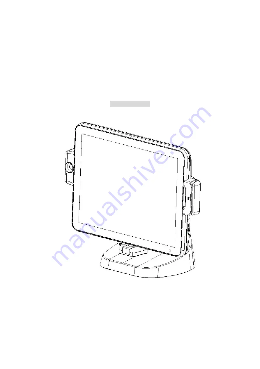
Page 1: ...i TP 2515 Fanless Full Flat POS Terminal User Manual Installation Guide Ver 1 0 Copyright Fametech Inc TYSSO 2018 ...
Page 2: ...R THE VENDOR SHALL NOT HAVE LIABILITY FOR ANY HARDWARE SOFTWARE OR DATA STORED OR USED WITH THE PRODUCT INCLUDING THE COSTS OF REPAIRING REPLACING OR RECOVERING SUCH HARDWARE SOFTWARE OR DATA WARNING The terminal has been tested and found to comply with the limits for a Class a digital device pursuant to Part 15 of the FCC rules These limits are designed to provide reasonable protection against ha...
Page 3: ...ire WARRANTY LIMITS If the product and the parts are disassembled by any person other than the authorized technicians the warranty will be terminated The users should consult his her dealer for any technical problems Warranty does not cover any damage caused by improper use TRADE MARKS AND SERVICE MARKS TYSSO is a registered trademark of FAMETECH INC Other brand and product names are trademarks an...
Page 4: ... with a third grounding pin This is a safety feature If your outlet does not accommodate the three wire plug have an electrician install a correct outlet or use an adapter to ground the appliance safely Do not leave out the safety purpose of the grounded plug Do not allow anything to rest on the power cord Do not locate the system where people may walk on the cord Do not make the power outlet and ...
Page 5: ... Specifications 2 1 3 Parts Descriptions 5 1 4 I O Ports Descriptions 7 2 POS Installation 8 2 1 Unpack Your POS 8 2 2 Install Your POS 9 Appendix 11 A Install LM 2010 X Secondary 2nd LCD Display Optional 11 OSD Control Button of the Secondary 2nd LCD Display 12 B Install the Modular Customer Display Optional 13 C Install the MSR i Button Module Optional 14 D Replace the Hard Disk Drive of Your PO...
Page 6: ...tion Guide x 1 Optional Accessories Magnetic Stripe Card Reader MSR i Button Module Modular Customer Display 2nd LCD Display Barcode Scanner Wi Fi VESA MOUNT Kit Chip Card Reader NFC Finger Print The Power Adapter is installed on the base and need not remove generally For more information relating to the other optional peripherals please contact the local representatives or technical support perso...
Page 7: ...S Parallel 1 x DB 25 Parallel Port optional USB 4 x USB type A 3 x USB 2 0 and 1 x USB 3 0 LAN 1 x RJ 45 Giga LAN Support 10 100 1000 Mbps VGA 1 x DB 15 Female Max Resolution 1920 x 1080 Cash Drawer 1 x RJ 11 12VDC 24VDC by jumper select DC Out 1 x 12VDC DC In 1 x 12VDC Others Power Adapter 12V 5A 60W External Power Adapter with Cable Head Lock hide in stand Power Adapter 100VAC 240VAC 50 60Hz Col...
Page 8: ...i directional comply with ISO 7811 and Track 1 2 3 HID USB Chip Card Reader Read write follow ISO7816 EMV specification and synchronous memory cards HID USB Optical Finger Print Optically scans and pixel resolution 512 dpi HID USB 3 1 Reader III MSR Bi directional comply with ISO 7811 and Track 1 2 3 HID USB Chip Card Reader Read write follow ISO7816 EMV specification and synchronous memory cards ...
Page 9: ...ew Left View Front View Right View Rear View Bottom View Note The Magnetic Stripe Card Reader MSR and i Button Module are optional parts and may not be included in the package Please purchase the optional parts separately ...
Page 10: ... 5 1 3 Parts Descriptions Front View Bottom View Base with AC Power Adapter LCD Touch Screen Power Indicator MSR Optional Base i Button Optional Base AC Power Cord Connector 2D Barcode Scanner ...
Page 11: ... 6 Rear View Bottom I O Ports MSR Optional Customer Display Optional Base Power Switch Cable Access Opening i Button Optional ...
Page 12: ...2VDC 24VDC selectable by jumper of mainboard 12V IN 12VDC Main Power Jack Connector with wire mount buckle to an AC power adapter installed on the base 12V OUT 12VDC jack for 2 nd LCD Display or other peripherals LAN 1 x RJ 45 connector with link act integrates speed LED LPT 1 x DB25 Parallel Port optional Note The LPT connector is optional and sealed without connector for standard version Please ...
Page 13: ... physical damage or missing parts please contact your supplier immediately Please keep all packing materials in case you need to ship back the device for service Unpacking The product and accessories are packed in a paperboard carton And it is wrapped by cushion materials for protection during shipping ...
Page 14: ...ower cord to the power source for example electrical outlet 5 Examine the Power Cord and the optional peripherals Make sure they are properly connected to the POS terminal Power Adapter on the base and Power Source 6 Turn on the switches of optional peripherals if installed 7 Turn on the power switch of the POS terminal on the back of the POS terminal Power Cord Electrical Outlet POS Terminal Cabl...
Page 15: ...install the POS terminal and the optional peripherals on a flat clean and stable location To prevent obstruction on the operator reserve appropriate space for the POS terminal and remove unnecessarily objects or items ...
Page 16: ... Display to the POS terminal e Install the 2nd LCD Display to the POS terminal Securing Screw Tapped Holes of the POS Terminal f Tighten the securing screws and re install the Top Cover back to the LCD Display Note The 2nd LCD Display is an Optional Accessory and is not included in the standard package Please contact your local representative for further information 2 nd LCD Display Securing Screw...
Page 17: ...isplay Press and pull downward to remove the back cover Control Buttons MENU Activate the OSD Menu LEFT RIGHT These two keys are used to select the adjustment items ENTER Press to confirm the setting POWER Use the power switch to turn the power ON or OFF Back Cover Control Buttons MENU LEFT RIGHT ENTER POWER LED Indicator ...
Page 18: ...y to the POS terminal e Install the Modular Customer Display to the POS terminal Securing Screw Tapped Holes of the POS Terminal f Tighten the securing screws and re install the Top Cover back to the Customer Display Note The Modular Customer Display is an Optional Accessory and is not included in the standard package Please contact your local representative for further information Modular Custome...
Page 19: ...tall the i Button Module to the POS terminal Note Connect the wired connector of i Button to the connector of POS terminal Connect the connector of i Button to the POS terminal c Secure the securing screws of i Button d Install the Back Cover of the i Button to the POS terminal Back Cover of i Button Protective Cover Protective Cover Securing Screws i Button Back Cover Removed ...
Page 20: ...al Note Connect the connector of MSR to the connector of POS terminal Connect the connector of MSR to the POS terminal f Secure the securing screws of MSR g Install the Back Cover of the MSR to the POS terminal MSR Module Back Cover Removed Back Cover of MSR Securing Screws ...
Page 21: ...POS Terminal b Remove the securing screw and pull out the Hard Disk Module c Install the new Hard Disk Module to the slot of the POS terminal d Secure the securing screw back to the POS terminal e Remember to re install the MSR Module back to the POS terminal if installed previously Or install the Protective Cover to the POS terminal Back Cover of MSR Securing Screws Hard Disk Module Hard Disk Mod...
Page 22: ...eplace a new hard disk 2 Secure the new HDD to the bracket 3 Re install the HDD Module with new HDD back to the POS terminal Note DO NOT push the HDD Module with force If the HDD Module cannot be installed back to the HDD Slot it might be the wrong direction when secure the HDD onto bracket HDD Bracket Securing Screws Hard Disk ...