11
8
27
19
20
18
17
3
4
25
28
7
12
26
5
15
13
29
23
14
6
7
24
Pa
10
9
B
A
30
32
32
33
31
31
30
22
*1
16
Pa
11
10
8
27
19
9
16
20
B
A
30
*1
32
32
33
18
17
30
30
35
37
21
3
4
25
28
7
5
15
13
29
23
32
14
6
7
24
36
12
26
38
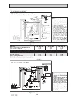
WATER SYSTEM DIAGRAM
8
•
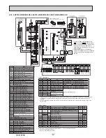
Refer to <Table 4-1 and 4-2> for the part names.
*1 Refer to the following section [Local system].
<E*ST20*-*M**C > (Split model system)
<EHST20*-MHCW> (UK Split model system) <Example>
<Figure 8-2>
<Figure 8-1>
Notes:
• To enable draining of the cylinder unit
an isolating valve should be posi
-
tioned on both the inlet and outlet
pipework.
• Be sure to install a strainer on the inlet
pipework to the cylinder unit.
• Suitable drain pipework should be at
-
tached to all relief valves in accord-
ance with your country’s regulations.
• A backflow prevention device must be
installed on the cold water supply
pipework (IEC 61770)
• When using components made from
different metals or connecting pipes
made of different metals insulate the
joints to prevent any corrosive reac
-
tion taking place which may damage
the pipework.
Flare connection
Flare connection
Cylinder unit
Cylinder unit
Drain
Drain
Drain
Drain
Drain
Drain
Cold water
Cold water
DHW
DHW
Local system
Refrigerant pipe
Water pipe
Local system
Flexible hose
(Temporary connection)
Water
supply
Notes:
• To enable draining of the cylinder unit
an isolating valve should be positioned
on both the inlet and outlet pipework.
No valve should be fitted between the
expansion valve (item 35) and the cyl
-
inder unit (safety matter).
• Be sure to install a strainer on the inlet
pipework to the cylinder unit.
• Suitable drain pipework should be at
-
tached to all relief valves in accord-
ance with your country’s regulations.
• When using components made from
different metals or connecting pipes
made of different metals insulate the
joints to prevent any corrosive reac
-
tion taking place which may damage
any pipework.
• Filling loop’s flexible hose must be re
-
moved following the filling procedure.
Item provided with unit as loose ac
-
cessory.
• Install the inlet control group (item 35)
above the level of the T&P relief valve
(item 21). This will ensure DHW tank
will not require drain-down to service/
maintain the inlet control group.
Refrigerant pipe
Water pipe
OCH570C
Summary of Contents for EHPT20X-MHCW
Page 108: ......


