70
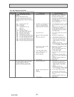
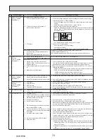
No.
Fault symptom
Possible cause
Explanation - Solution
4
LED2 on FTC is off.
(See "6. WIRING
DIAGRAM".)
<FTC powered on independent source>
1.
FTC is not supplied with 220 to 240 V AC.
1.
Check the voltage across the L and N terminals on the indoor power supply
terminal block. (See "7. FIELD WIRING".)
• When the voltage is not 220 to 240 V AC, check for faulty wiring to power
supply.
• When the voltage is 220 to 240 V AC, go to 2. below.
2. There are problems in the method of
connecting the connectors.
2.
Check for faulty wiring between the connectors.
• When the connectors are wired incorrectly re-wire them correctly referring
to below. (See "7. FIELD WIRING" and a wiring diagram on the control and
electrical box cover.)
L
N
CN01
CN01
S1
S2
S3
• If no problem found with the wiring, go to 3. below.
3. FTC failure
3. Check the FTC control board.
• Check the fuse on FTC control board.
• Check for faulty wiring.
• If no problem found with the wiring, the FTC control board is faulty.
When LED1 on FTC is lit.
Recheck the refrigerant address setting on the outdoor unit.
Set the refrigerant address to “0”.
(Set refrigerant address using SW1(3-6) on outdoor controller circuit board.)
Incorrect setting of refrigerant address for
outdoor unit.
(None of the refrigerant address is set to "0".)
5
LED2 on FTC is
blinking.
(See "6. WIRING
DIAGRAM".)
When LED1 is also blinking on FTC .
Check for faulty wiring between FTC and outdoor unit.
Faulty wiring between FTC and outdoor unit
When LED1 on FTC is lit.
1.
Faulty wiring in main remote controller
Multiple indoor units have been wired to a
single outdoor unit.
1.
Check for faulty wiring in main remote controller.
The number of indoor units that can be wired to a single outdoor unit is one.
Additional indoor units must be wired individually to a single outdoor unit.
2.
Short-circuited wiring in main remote control
-
ler
2.,3.
Remove main remote controller wires and check LED2 on FTC. (See "6.
WIRING DIAGRAM".)
• If LED2 is blinking check for short circuits in the main remote controller wiring.
• If LED2 is lit, wire the main remote controller again and:
- if LED2 is blinking, the main remote controller is faulty;
-
if LED2 is lit, faulty wiring of the main remote controller has been corrected.
3. Main remote controller failure
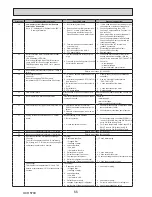
6
LED4 on FTC is off.
(See "6. WIRING
DIAGRAM".)
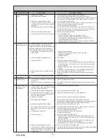
1. SD memory card is NOT inserted into the
memory card slot with correct orientation.
1. Correctly insert SD memory card in place until a click is heard.
2. Not an SD standards compliant memory card. 2. Use an SD standards compliant memory card. (Refer to installation manual,
"5.8 Using SD memory card".)
LED4 on FTC is
blinking.
(See "6. WIRING
DIAGRAM".)
1. Full of data.
1.
Move or delete data, or replace SD memory card with a new one.
2. Write-protected.
2.
Release the write-protect switch.
3. NOT formatted.
3.
Refer to installation manual, "5.8 Using SD memory card".
4.
Formatted in NTFS file system.
4.
FTC is Not compatible with NTFS file system. Use an SD memory card for
-
matted in FAT file system.
7
No water at hot tap.
1. Cold main off
1. Check and open stop cock.
2. Strainer (local supply) blocked.
2.
Isolate water supply and clean strainer.
8
Cold water at tap.
1.
Hot water run out.
1.
Ensure DHW mode is operating and wait for DHW tank to re-heat.
2. Prohibit, schedule timer or holiday mode se-
lected or demand control input (IN4) or smart
grid ready (switch-off command).
2.
Check settings and change as appropriate.
3.
Heat pump not working.
3. Check heat pump – consult outdoor unit service manual.
4. Booster heater cut-out tripped.
4. Check booster heater thermostat and press reset button if safe.
Reset button is located on the side of booster heater, covered with white rub
-
ber cap. See "4. PART NAMES AND FUNCTIONS" to find out its position.
5.
The earth leakage circuit breaker for booster
heater breaker (ECB1) tripped.
5. Check the cause and reset if safe.
6. The booster heater thermal cut-out has
tripped and cannot be reset using the manual
reset button.
6. Check resistance across the thermal cut-out, if open then the connection is
broken and the booster heater will have to be replaced.
Contact your Mitsubishi Electric dealer.
7. Immersion heater cut-out tripped.
7. Check immersion heater thermostat and press reset button, located on im-
mersion heater boss, if safe. If the heater has been operated with no water
inside it may have failed, so please replace it with a new one.
8. Immersion heater breaker (ECB2) tripped.
8. Check the cause and reset if safe.
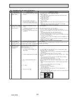
9.
3-way valve fault
9.
Check plumbing/wiring to 3-way valve.
(i) Manually override 3-way valve using the main remote controller. (Refer to
<Manual operation> in "9-4. Service menu") If the valve does not still func
-
tion, go to (ii) below.
(ii) Replace 3-way valve coil. If the valve does not still function, go to (iii) be
-
low.
(iii) Replace 3-way valve. (Refer to "11. DISASSEMBLY PROCEDURE".)
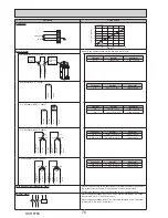
YELLOW
YELLOW
BLACK
BLACK
Modified settings
(Separate power
supply to the
cylinder unit)
Cylinder unit
control board
White
OCH570C
Summary of Contents for EHPT20X-MHCW
Page 108: ......

