2Unpacking to Installation
Installation 2-10
2.2.3 Installation procedures
The installation procedure of the robot arm is shown below.
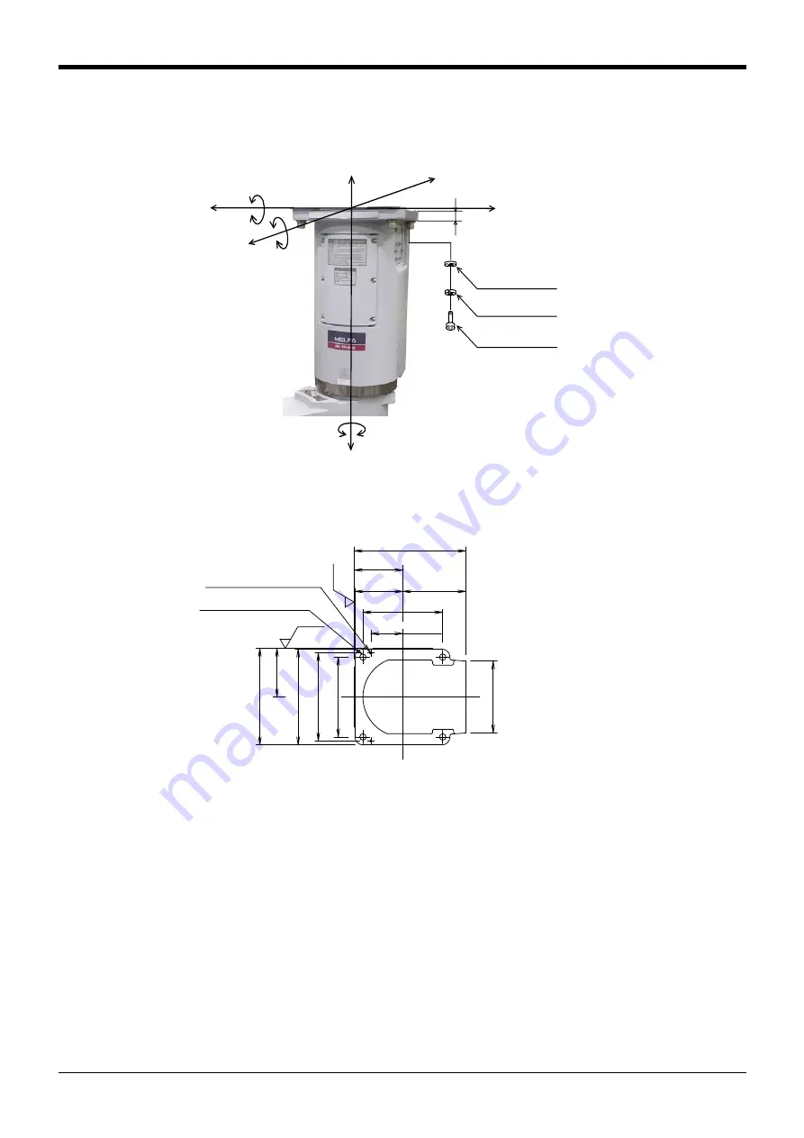
Fig.2-4 : Installation dimensions
1) The robot installation surface has been machine finished. Use the installation holes (4-φ16 holes) opened
at the four corners of the base, and securely fix the robot with the enclosed installation bolts (hexagon
socket bolts). (Recommended tightening torque: 92.1 N.m)
2) Install the robot on a level surface.
3) It is recommended that the surface roughness of the table onto which the robot is to be installed by 6.3 Ra
or more. If the installation surface is rough, the contact with the table will be poor, and positional deviation
could occur when the robot moves.
4) When installing, use a common table to prevent the position of the devices and jigs subject to robot work
from deviating.
5) The installation surface must have sufficient strength to withstand the arm reaction during operation, and
resistance against deformation and vibration caused by the static (dynamic) load of the robot arm and
peripheral devices, etc.
6) After installing the robot, remove the fixing plate and transportation tool.
7) If you operate the robot at a high speed, reaction forces are applied to the installation stand by the robot's
operation. Make sure that the installation stand on which the robot is placed has sufficient strength and
4-φ16 installation holes
180
120
122
240
122
200
200
(Installation
reference surface)
(Installation
reference surface)
242
280
(158)
220
80
Ra6.3
Ra6.3
2-φ6 holes
(for φ8 positioning pins)
F
H
F
V
F
H
F
H
F
H
M
L
M
L
F
V
M
T
25
(4箇所)
バネ座金
平座金
4-M12×45
(Four positions)
Spring washer
Plain washer
<Detail of installation dimension>
(Base section of a robot arm))


