background image

Types

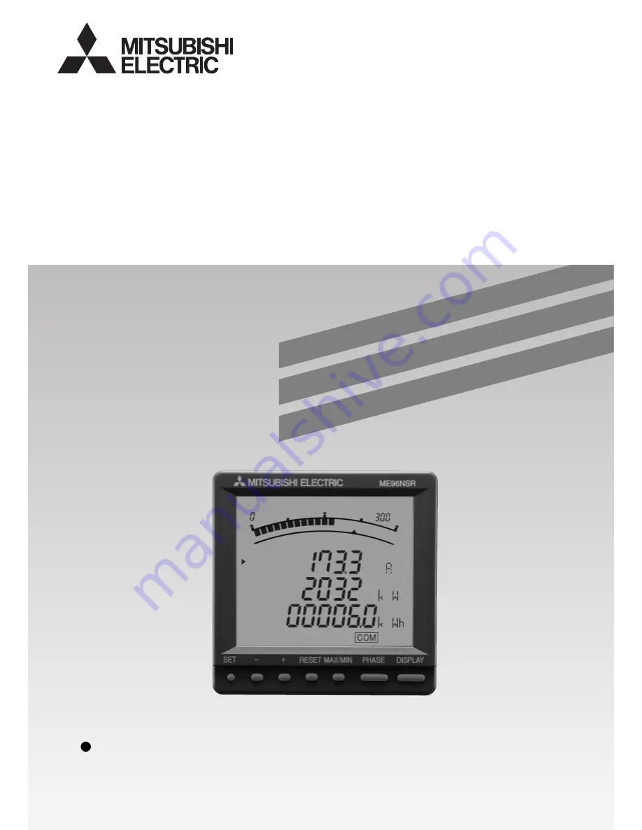
ME96NSR

ME96NSR-MB

User’s Manual

Before operating the instrument, you should first read thoroughly 
this operation manual for safe operation and optimized 
performance of the product.

Deliver this user’s manual to the end user.

MITSUBISHI Electronic Multi-Measuring Instrument

Summary of Contents for ME96NSR

Page 1: ... Before operating the instrument you should first read thoroughly this operation manual for safe operation and optimized performance of the product Deliver this user s manual to the end user MITSUBISHI Electronic Multi Measuring Instrument ...

Page 2: ...nd to various I O by installing the optional plug in module About the Optional Plug in Module Sold Separately ME 4201 NS96 ME 0052 NS96 2 ME 0040C NS96 Type name of optional plug in modules Pulse output 2 points Analog output 4 circuits I O specifications Digital input 5 points 4 points Digital output 1 1 point 2 points Communication CC Link 1 The digital output of the ME 4201 NS96 is the alarm ou...

Page 3: ...tal Output Test 36 6 Operation 6 1 Display Change 37 6 2 Phase Change 37 6 3 Bar Graph Display 38 6 4 Maximum Value and Minimum Value Display 39 6 5 Cyclic Display Change 40 6 6 Alarm Display and How to Cancel 41 6 7 Harmonics Display 42 6 8 Expanded Counting Display 43 6 9 Display of Digital Input and Digital Output 44 6 10 Set Value Confirmation Mode 44 7 Others 7 1 How to Rearrange the Display ...

Page 4: ...y a qualified electrician The instrument must not be powered and used until its definitive assembly on the cabinet s door Verify the following points Auxiliary power supply and measuring ratings Current circuits C1 C2 and C3 are Measurement category 1 Voltage circuits P1 P2 and P3 are Measurement category 3 The instrument is to be mounted on a panel All connections must be kept inside the cabinet ...

Page 5: ...e The period of guarantee is earlier date of either 18 months from the manufacture date or 1 year from the sale date except in the case that the failure has been caused by bad handling of the product provided that it has been installed according to the manufacture s instructions Operation Instructions CAUTION When the external terminals are connected to the external equipments the instrument and t...

Page 6: ...nductive cabinet is used Six faces of a cabinet have to be ensured conductivity for each other A cabinet has to be connected to earth by a thick wire of low impedance Holes on faces of cabinet have to be 10 cm or less in diameter The terminals for protective earth and functional earth have to be connected to earth by a thick wire of low impedance A terminal for protective earth is important not on...

Page 7: ...a phased system expansion plan Remote Input Output Functions It can expand the remote input output functions to the ModBus communication It can observe the state of five digital inputs and control two digital outputs with the electric power monitor And because the latch function is provided in the remote digital input and the pulse signal of 30ms or more can be maintained it is possible to use it ...

Page 8: ...ed with the bar graph They show the phase for each of the digital displays They show the unit for each of the digital displays When it is blinking the instrument is counting active energy It means that the digital displays are harmonics values It shows that the instrument is equipped with a communication function It blinks under the condition of a communication error They show that the upper limit...

Page 9: ...s is changed to next content The display of set up menu appears At the final contents of the setup The End display appears At the final contents of the setup in the simplified set up menu After the setup contents are saved the display on operation mode appears if it is the End display After the setup contents are not saved the display on operation mode appears if it is the CANCEL display The displ...

Page 10: ...Operation mode Test mode Set up Menu 8 Instantaneous value cyclic display change Maximum value and minimum value cyclic display change Instantaneous value display Maximum value and minimum value display Instantaneous value cyclic phase change Maximum value and minimum value cyclic phase change Diagram of Each Mode This meter has 4 kinds of function modes Use it at each mode according to your requi...

Page 11: ...alue displays are automatically changed every 5 seconds see page 40 Maximum value and minimum value cyclic phase change Maximum value and minimum value phases are automatically changed every 5 seconds see page 40 Set up mode In this mode all the setting items including primary voltage primary current and so forth can be set Set necessary items before operation see pages 12 to 31 Set value confirma...

Page 12: ...t up mode Set up menu 1 Set up menu 2 Simplified set up menu blink extinction CC Link station number Initializing process Shift automatically Example Example of set value confirmation mode For correct measurement it is necessary to set the primary voltage and the primary current etc in the set up mode It can set necessary items after it shifts from the Operation mode to set up mode Items are not s...

Page 13: ... Alarm delay time Action Select a set value Shift to the End screen Select CANCEL Cancel the setting Display the type of option unit Initializing of instrument Key operation Press it for 2 seconds Press it several times Press it Press it Press it several times Press it Press it Press it Press it Press it for 1 second Press it or or or Omitted in figure Arrow in figure Set up mode or set value conf...

Page 14: ...digital output DI DO only when option module is installed VA Three phase 4 wire only P01 P02 P03 P04 P05 P06 P07 P08 P09 P10 P11 P12 P13 P00 A DA V W PF var Hz varh VA Wh HI HV DI Wh Exported active energy DO Display pattern 4 Direct voltage DISPLAY SET 4 Set up the rated voltage for scaling of the bar graph If you set YES on set up No 3 this display does not appear 110V 63 5V 173V 100V 190V 110V ...

Page 15: ... can be moved to right by the SET The setting digit can be moved to left by the DISPLAY The number of settable digits is 3 digits Setting is available in the range from 60V to 750kV 750000V If it is set to other range than 60V to 750kV error display E05 appears At the moment of the error display press the SET and review the set value and set it once again When the SET is pressed at the most lower ...

Page 16: ...inutes 20 minutes 25 minutes 30 minutes Note Even when the display pattern not display the current demand this screen appears If the current demand is not necessary press the SET as it is In the case of use only by the Set up Menu 1 basic set up go to 5 Operation in page 37 In the case to use additional functions go to Set up Menus 2 to 8 in page 17 to 32 4 Set up Set up Menu 1 4 2 Basic Set up If...

Page 17: ... rates 3 Set the ModBus baud rate In the case of CC Link this display does not appear 2400 bps 4800 bps 9600 bps 19 2 kbps 38 4 kbps Stop bit 1 Stop bit 2 5 ModBus stop bit 5 Set the ModBus stop bit In the case of CC Link this display does not appear SET DISPLAY SET DISPLAY SET DISPLAY SET DISPLAY 4 ModBus parity 4 Set the ModBus parity In the case of CC Link this display does not appear Settable ...

Page 18: ...en it is not set to ON changed station number and baud rate do not become valid 9 Digital input reset 9 Set the digital input DI reset method Without digital input this display does not apper DISPLAY SET HoLd Manual method Auto Automatic method Note When selected the manual method HoLd input state is kept until the cancel operation by the hand For the method of the cancel operation refer to page 4...

Page 19: ...in the table on page 50 2 Set the maximum scale of Active power The maximum scale is set in the range of about 40 to about 120 of the rated full load power Note This insturument s rating is 100 value The maximum scale value becomes the value in the table on page 50 3 Set the single double deflection of Active power When the and are pressed the scale value of bar graph flickers at single double def...

Page 20: ...measurement on Harmonic measurement value is displayed off Harmonic measurement value is not displayed on The state of the digital input output is displayed off The state of the digital input output is not displayed DISPLAY SET DISPLAY SET DISPLAY SET DISPLAY SET 3 Set the display of the digital input output state When the ME 0052 NS96 or ME 0040C NR96 type optional plug in module is not installed...

Page 21: ...t DISPLAY SET 8 Reactive power display digit 8 Set the reactive power display digit DISPLAY SET 9 Apparent power display digit 9 Set the apparent power display digit SET Set up menu According to the set up diagram page 13 save the changed contents or continue to the other set up menu Note In No t to No o the measurement element that doesn t exist in the display pattern skips the setting 888 3 digi...

Page 22: ... Note 3 The upper alarm of A and DA is judged from the phase of 1 2 3 and N The lower alarm of A and DA is judged from the phase of 1 2 and 3 N is excluded Note 4 The alarm of the total distortion ratio is judged from the phase of 1 2 and 3 N is excluded DISPLAY SET Three phase 3 wire Three phase 4 wire Alarm item A DA AN DAN upper limit A DA lower limit V upper limit V lower limit W var upper lim...

Page 23: ...DISPLAY SET Method Automatic Auto Manual HoLd Cancel method When there is no alarm occurrence condition alarm is automatically reset 4 Set the alarm delay time If the condition that the limit was exceeded continues more than the delay time it will be in the alarm condition And if it dose not continue at this time the max min value is not updated see page 41 0 seconds 5 seconds 10 seconds 20 second...

Page 24: ...3 Σvar VA1 VA2 VA3 ΣVA PF1 PF2 PF3 ΣPF CH4 Hz HI1 HI2 HI3 HIN HV1N HV2N HV3N Set the set up menu number to 6 Set as shown in the right display Note DA current demand HI harmonics current total RMS value HV harmonics voltage total distortion ratio 4 Set up 4 7 Analog Output Set up Set up Menu 6 In the operation mode press the SET and the RESET simultaneously for 2 seconds or more and the following ...

Page 25: ...et up Analog outputs CH2 to CH4 are set also in the same method as 1 analog output CH1 measurement item set up Analog outputs CH2 to CH4 are set also in the same manner as 2 analog output CH1 detailed set up 4 Analog output CH2 to CH4 detailed set up Set if the undefined analog output is cut 5 Analog output limit on Cut the undefined analog output oFF Don t cut the undefined analog output 5 Set of...

Page 26: ...ctive energy No output Display Wh Wh varh LAG varh LEAD varh LAG varh LEAD non Settable elements DISPLAY SET DISPLAY SET 3 Set the element to be output to pulse output 2 Pulse output 2 is set also in the same method as q pulse output item 1 set up At initial imported lag reactive energy is set to pulse output 2 In case of reactive energy kW in the above table is exchanged into kvar and kWh into kv...

Page 27: ...or 1 100 time when load is large pulse output cannot follow and the counting pulse may be decreased SET Set up menu According to the set up diagram page 13 save the changed contents or continue to the other set up menu 5 Pulse width 5 Set the pulse width of output pulse 4 Set up Set up Menu 7 4 8 Pulse Output Set up ...

Page 28: ... DISPLAY SET DISPLAY SET DISPLAY SET DISPLAY SET 1 Phase wire Set the set up menu number to End Set as shown in the right display Press the PHASE and the DISPLAY simultaneously for 1 second or more 1 Set the phase wire 1 3P3W 2CT 2 3P3W 3CT 3 3P4W 00 P00 to 13 P13 0 direct input 1 using VT 2 Display pattern 2 Set the display pattern 3 Using VT direct input 3 Set the using VT or direct input withou...

Page 29: ... Voltage values the top 3 digits 0 to 9 Example Set up to 10000V Exponent values 2 Voltage values 100 7 CT primary current 7 Set the primary current values of CT It is set by the top 2 digits current values and the exponent values 10 to the n 1 th power The set up order is the exponent values and the current values Exponent values 0 10 1 0 1 time 1 100 1 time 2 101 10 times 3 102 100 times 4 103 1...

Page 30: ... 38 4kbps DISPLAY SET 2 ModBus parity 2 Set the ModBus parity In the case of CC Link this content cannot be set 0 non 1 odd 2 even DISPLAY SET 3 ModBus stop bit 3 Set the ModBus stop bit In the case of CC Link this content cannot be set 1 1 2 2 DISPLAY SET DISPLAY SET 4 CC Link station number 4 Set the CC Link station number In the case of ModBus this content cannot be set Address 01 to 64 5 CC Li...

Page 31: ...ve the changed contents or continue to the other set up menu SET 3ModBus stop bit 1 1 2 2 4CC Link station number 01 to 64 6Communication module reset 0 OFF 1 ON 5CC Link Baud rates 1 156kbps 2 625kbps 3 2 5Mbps 4 5Mbps 5 10Mbps yVT primary voltage Exponent value 0 60 to 999V 1 1000 to 9990V 2 10000 to 99900V 3 100000 to 750000V Voltage value 100 digits 10 digits 1 digit 0 to 9 0 to 9 0 to 9 uCT p...

Page 32: ...ent and How to Test 5 1 Analog Output Adjustment Set up menu DISPLAY SET DISPLAY SET DISPLAY SET SET Set up menu According to the set up diagram page 13 save the changed contents or continue to the other set up menu 20mA 4 Zero adjustment 䉭mA INPUT INPUT INPUT 20mA 4 Span adjustment 䉭mA Single deflection 0 䉭mA Double deflection 0 q Zero Adj for CH1 w Span Adj for CH1 CH2 CH3 and CH4 can be adjuste...

Page 33: ...f power failure It is impossible to test without the option module 5 2 Alarm Output Test q Test the alarm output When the is pressed the display and the contact output are changed as following Test menu q Alarm output test SET SET Set the test menu number to 1 Set as shown in the right display Test menu In case of test the other output according to the 5 3 to 5 5 continue to the test When the test...

Page 34: ... the test is finished turn off the power supply q Analog output CH1 test w Analog output CH2 test SET e Analog output CH3 test SET SET r Analog output CH4 test q Test the analog output CH1 When the is pressed the display and the analog output CH1 are changed as following 50 output 100 output 0 output w Test the analog output CH2 When the is pressed the display and the analog output CH2 are changed...

Page 35: ... Output Test Test menu SET SET SET Set the test menu number to 3 Set as shown in the right display Test menu In case of test the other output according to the 5 2 to 5 5 continue to the test When the test is finished turn off the power supply q Pulse output CH1 test w Pulse output CH2 test q Test the pulse output CH1 When the is pressed the display and the pulse output are changed as following oFF...

Page 36: ...as shown in the right display Test menu In case of test the other output according to the 5 2 to 5 4 continue to the test When the test is finished turn off the power supply q Digital output CH1 test SET w Digital output CH2 test Note An initial value of each CH of this test mode is Open If CH is changed or this test mode ends the output becomes Open q Test the digital output CH1 When the is press...

Page 37: ...ched over This shows the second display among the 4 display DISPLAY DISPLAY DISPLAY Display items and sequences vary with display patterns P01 to P13 and additional display As for detailed display pattern refer to page 48 49 Reference By pressing PHASE the current phase and the voltage phase will switch over Example of display change Current average value Power total Voltage average value Current ...

Page 38: ...nt item to be displayed on bar graph can be selected By displaying others than the measurement items digitally displayed 4 elements can be displayed at once Explanation of bar graph In the bar graph measurement elements shown by or are displayed As for voltage current active power reactive power power factor and frequency they can be displayed on the bar graph even if they are not set to display p...

Page 39: ...values are reset Delay time of max min value If max min value doesn t continue for a long time since delay time it doesn t update it Delay time is set by set up menu 5 Alarm delay time delay time of max min value Please set the delay time when you do not want to make the maximum value updated in the condition of becom ing a value with excessive only way short time such as starting currents of the ...

Page 40: ...yclic display change screen the display blinking 3 times Note 2 By pressing any other key than the SET it goes back to manual change Note 3 In the cyclic display change drawing number is not displayed Cyclic phase change When PHASE is pressed for about 2 seconds the cyclic phase change appears It is possible to cyclic phase change it even on the maximum value and minimum value display Display for ...

Page 41: ...N AVG Σ DM of the measurement element are blinking There is no blink when the element is not a display Note 3 Only ALARM HI or LO blinks on the maximum value and minimum value display Note 4 In the harmonics only total distortion ratio and RMS value are blinking The display of degree is not blinking Note 5 The alarm is generated on all the following conditions 1 The display pattern is set to P00 2...

Page 42: ...PHASE PHASE Current total phase 1 Current 1st phase 1 Voltage total phase 1 N Voltage 1st phase 1 N Voltage 3rd phase 1 N Voltage 13th phase 1 N Current total phase N RMS Current 1st phase N RMS Current 3rd phase N RMS Current 13th phase N RMS Current total phase 2 Current total phase 3 Distortion ratio RMS Current 1st phase 2 Current 1st phase 3 RMS Current 3rd phase 1 Current 3rd phase 2 Current...

Page 43: ...h division there is a dead region It is suitable for the counting of equipment with the private electric generator var var W W Exported lag Exported lead Imported lead Imported lag Exported lag Exported lead Imported lead Imported lag 2 quadrants counting Imported lag and Exported lead are counted as divi sion of one Imported lead and Exported lag are counted as division of one The dead region is ...

Page 44: ...e latch is canceled by pressing RESET for 2 seconds or more Note To display the digital input it is needed to set display of the digital input output to on The initial content is set to on 6 10 Set Value Confirmation Mode When you want to confirm the set value you use the set value confirmation mode In this mode the contents of the set up items cannot be set which prevents changing other set value...

Page 45: ...DISPLAY Screen 4 2 Upper stage measurement item 4 Middle stage measurement item 5 Lower stage measurement item 6 Screen 4 3 Upper stage measurement item 7 Middle stage measurement item 8 Lower stage measurement item 9 Screen 4 4 Upper stage measurement item 10 Middle stage measurement item 11 Lower stage measurement item 12 Screen 2 1 Upper stage A Middle stage V Lower stage Wh Screen 2 2 Upper st...

Page 46: ...play By or set the unit code of the lower stage to no display and press SET 9 Set the display 4 3 to no display By or select no and press SET Note When the display 4 3 is set to no display the display 4 4 is also set to no display automatically Back to the upper stage of the display 4 1 1 The following measurement item cannot be set by the display pattern P00 Set them separately in the set up menu...

Page 47: ...imit var upper limit var lower limit PF upper limit PF lower limit Hz upper limit Hz lower limit Harmonic current total RMS value Harmonic current phase N RMS value 2 Harmonic voltage total distortion ratio 1 The apparent power is not included in the alarm element 2 Phase N is a alarm element to be independent Alarm item 1 Phase wire 3P3W 3P4W 3P3W 3P4W 3P4W 3P3W 3P4W 3P3W 3P4W 3P4W 3P4W 3P4W 3P3W...

Page 48: ...3N A1 A2 A3 DA1 DA2 DA3 A1 A2 A3 DA1 DA2 DA3 A V Wh W1 W2 W3 A AN A AN A PF VA A VA Wh A AN A AN V1N V2N V3N V1N V2N V3N DA1 DA2 DA3 V1N V2N V3N DA V Wh var1 var2 var3 A PF Hz A PF Wh A AN A AN V1N V2N V3N A AN W V Wh VA1 VA2 VA3 A AN A Hz Wh DA DAN A AN DA DAN A AN PF1 PF2 PF3 A AN DA DAN DA DAN V Hz Wh V Hz varh A AN Exported lead reactive energy Exported lead reactive energy Exported lead react...

Page 49: ...7 NO 8 NO 9 NO 10 NO 11 NO 12 NO 13 NO 14 Upper stage Middle stage Lower stage Upper stage Middle stage Lower stage Upper stage Middle stage Lower stage Upper stage Middle stage Lower stage Upper stage Middle stage Lower stage Upper stage Middle stage Lower stage Upper stage Middle stage Lower stage Upper stage Middle stage Lower stage Upper stage Middle stage Lower stage Upper stage Middle stage ...

Page 50: ...2000 2500 3000 4000 5000 640 k 640 k 800 k 800 k 1000 k 1000 k 1200 k 1200 k 1600 k 1600 k 2000 k 2000 k 2400 k 2400 k 3200 k 3200 k 4000 k 4000 k 1 At the direct voltage setting VT ratio 1 Specific power value is according to the following 2 For convenience of the scale it is rounded the good number Measurement element Maximum scale value In the case of direct voltage setting In the case of VT co...

Page 51: ...A 3 6kA 4kA 4 5kA 4 8kA 5kA 6kA 6 4kA 7 2kA 7 5kA 8kA 9kA 10kA 12kA 15kA 16kA 18kA 20kA 22kA 24kA 25kA 30kA 32kA 36kA 40kA kA unit A unit kA unit A unit STEP 1 2 3 4 5 6 7 8 9 10 11 12 13 14 15 16 17 18 19 20 21 22 23 24 25 26 27 28 29 30 31 32 33 34 35 36 37 38 39 40 41 42 43 44 45 46 47 48 49 50 51 52 53 54 55 56 57 58 59 60 61 62 63 64 65 66 67 68 180W 200W 220W 240W 250W 300W 320W 360W 400W 45...

Page 52: ... 480kvar 500kvar 600kvar 640kvar 720kvar 750kvar 800kvar 900kvar 1000kvar 1200kvar 1500kvar 1600kvar 1800kvar 2000kvar 2200kvar 2400kvar 2500kvar 3000kvar 3200kvar 3600kvar 4000kvar 4500kvar 4800kvar 5000kvar 6000kvar 6400kvar 7200kvar 7500kvar 8000kvar kvar unit 1Mvar 1 2Mvar 1 5Mvar 1 6Mvar 1 8Mvar 2Mvar 2 2Mvar 2 4Mvar 2 5Mvar 3Mvar 3 2Mvar 3 6Mvar 4Mvar 4 5Mvar 4 8Mvar 5Mvar 6Mvar 6 4Mvar 7 2M...

Page 53: ...display 9999 it becomes the upper limit of the display 9999 When it exceeds the upper limit of the display 9999 it becomes the upper limit of the display 9999 When it is below 44 5Hz or over 99 9Hz is displayed At measuring the distortion ratio When input voltage is 0V it becomes For each phase When the frequency is below 44 5Hz is displayed for all phases At measuring the distortion ratio When in...

Page 54: ...red values of W var cosf are including large errors Measured values of cosf is including large error Maximum value is not held Maximum value and minimum value changed Index indicator and alarm value changed The harmonic total RMS value of harmonic current HI is largely different from current A value The active power value calculated by the current the voltage and the power factor is largely differ...

Page 55: ...55 Installation 1 Dimensions ME96NSR ME96NSR MB Option cover With the optional plug in module 91 6 PANEL CUT 91 6 PANEL CUT 106 9 86 2 20 7 95 8 COVER 95 8 COVER ...

Page 56: ...56 Installation 1 Dimensions Optional Plug in Module 75 8 61 3 46 8 81 2 25 2 17 1 88 8 ...

Page 57: ...ug in module is installed Combine the slot of the basic de vice and the convex part of the op tional plug in module Note Please do not tighten too strongly to prevent panel and screw from breaking Tightening torque for this product 0 3N m to 0 5N m Half the torque applied normally for this type of screw Also please tighten the upper and lower screws at the same time 1 Dimensions of the panel The p...

Page 58: ...nput and output terminals of the basic device qStrip the top of the cables or crimp the ferrule wSlacken screws of the terminal block and insert the cables into terminal hole eFasten the terminal screws by the regulation fastening torque Terminals of the optional plug in module qStrip the top of the cables or crimp the ferrule wInsert the cables with pushing the lever and connect by releasing the ...

Page 59: ...ding which can result in insulation breakdown of the primary winding and inter phase short circuiting in the end Do not use unsuitable electric wire Electric wire size should be suitable for rated current and voltage Use of unsuitable electric wire can cause a fire Do not impress unusual voltage At the time of the resisting pressure examination of the high voltage apparatus carry out grounding to ...

Page 60: ...ise there will be a false operation Note Three phase 4 wire type Example of ME96NSR in case with VT Three phase 4 wire type Example of ME96NSR MB in case for direct input C1 PN P3 P2 P1 C3 C3 C2 C2 C1 T MA NC MB NC SLD SLD Ter Tー Protective Earthing Load ー RS485 ModBus k K L 3 2 1 0 K L l k l K L k l RS485 ModBus C1 PN P3 P2 P1 C3 C3 C2 C2 C1 NC MA NC MB NC NC NC NC NC u v u v u v U V U V U V k K ...

Page 61: ...connected to earth by a thick wire of low impedance 4 Keep the distance between ModBus link to power line 5 When the setting is 2CT the use by 3CT wiring does not correctly measure for phase 2 Note Protective Earthing Auxiliary power supply 100 to 240 VAC 100 to 240 VDC 1 For a low voltage circuit grounding of the secondary sides of VT and CT in not necessary 2 Do not connect to NC terminal U V u ...

Page 62: ...hould not bunch them And use the shielded cables or twisted pair cables not to be affected the noise serge and induction Also the wiring cables are to be as short as possible 3 In case of ME96NSR MB with ME 4201 NS96 the ModBus interface and the analog outputs do not have the insulation between them Note Conditions Length Below 600V power lines Other power lines 30cm or more 60cm or more ME 4201 N...

Page 63: ...tween CC Link cables to power lines Refer to Installation instruction in Safety Precaution 4 Fill the requirements of total wire distance station distance and terminal resistance value according to baud rate and type of cable As for detail of the requirements refer to the operation manual for CC Link master unit 5 To the units of both the end of CC Link line the terminal resistors should be attach...

Page 64: ...2 W3 Σ var var1 var2 var3 Σ VA VA1 VA2 VA3 Σ PF PF1 PF2 PF3 A1 A2 A3 Aavg DA1 DA2 DA3 DAavg V12 V23 V31 VLLavg Σ W Σ var Σ PF LCD with backlight A DA V W var VA PF 4 digits or 3 digits Hz 3 digits Energy 6 digits HV HI Distortion ratio 3 digits HV HI RMS 4 digits or 3 digits 21 segments with scales Display on it which selected upper middle or lower of the digital display Without energy and harmoni...

Page 65: ... 64 a number of units occupied by 1 station b number of units occupied by 2 stations c number of units occupied by 3 stations d number of units occupied by 4 stations Condition 2 16 A 54 B 88 C 2304 A number of remote I O stations B number of remote device stations C number of local stations 1 to 64 Numbers of occupied stations CC Link version Baud rate Maximum number of connected units Remote sta...

Page 66: ...dule reset Digital input reset Current maximum scale Active power maximum scale Active power scale type Reactive power maximum scale Power factor scale Expanded counting Harmonics Digital input output Back light ON OFF Current display digit Voltage display digit Active power display digit Reactive power display digit Apparent power display digit Alarm item 1 Alarm value 1 Alarm item 2 Alarm value ...

Page 67: ... change are shown in shade Set up procedures SET SET SET SET SET SET RESET Pressing simultaneously for 2 seconds Operation mode Secondary current Direct voltage Display pattern Phase wire Set up menu Set the set up menu number to 1 and press SET It is set to no direct input at initial content so press as it is SET Using VT or direct input It is set to 3P4 Three phase 4 wire at initial content so p...

Page 68: ... to 10 kW pulse and press SET SET SET SET Pulse width Set up menu End display Operation mode It is set to 0 125s at initial content so press as it is SET Set the set up menu number to End and press SET Press once again Set up change is saved SET Measurement gets started with changed set up contents SET SET SET Supplementary As for detailed setting contents refer to pages 12 to 28 ...

Page 69: ...69 ...

Page 70: ... Deungchon Dong Kanguseo Ku Seoul 157 030 Korea 24th Fl Galleria Corporate Center Edsa Cr Ortigas Ave Quezon City Metro Manila Philippines 6F NO 105 Wu Kung 3rd rd Wu Ku Hsiang Taipei Hsien Taiwan 77 12 Bumrungmuang Road Klong Mahanak Pomprab Bangkok 10100 62 0 21 6621780 82 2 3668 6567 63 0 2 643 8691 886 0 2 2298 8889 66 223 4220 3 Vietnam 47 49 Hoang Sa St Da Kao Ward D 1 HCMC 84 8 910 4763 475...

Reviews: