38
GB
<PAC-PH02EHY-E> <PAC-PH03EHY-E>
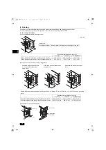
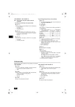
Step 1. Installing and wiring the terminal block to the
control box
• Installing the terminal block for the panel heater
[Fig. 9.1.1.1]
[Fig. 9.1.1.2]
[Fig. 9.1.1.3]
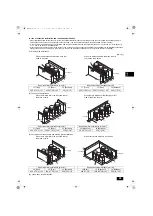
Step 2. Wiring the panel heater to the control box
[Fig. 9.2.1.1]
[Fig. 9.2.1.2]
[Fig. 9.3.2]
See the electrical wiring diagram.
[Fig. 9.4.1]
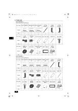
10. Reassembly
Reinstall the parts in the reverse order in which they were removed.
<PAC-PH01EHY-E>
[Fig. 10.0.1]
[Fig. 10.0.2]
[Fig. 10.0.3]
<PAC-PH02EHY-E> <PAC-PH03EHY-E>
[Fig. 10.1.1]
[Fig. 10.1.2]
[Fig. 10.1.3]
<A> Remove the two screws holding the control board assy
to the control box.
A
Control box
B
Control board assy
<A> Hook the top part of the terminal block on the sheet
metal of the control board assy, and hold them together
with the two removed screws.
A
Terminal
<A> Connect the fuse wiring to CN510 on the circuit board.
A
Fuse wiring
B
Fuse wiring connector
<A> Connect the panel heater wirings to the correct terminal
block. (See the table below.)
<B> CORRECT
<C> INCORRECT
A
Terminal
* See the figure <C> for how to connect two ring terminals to
a single terminal.
Location of panel heater
wiring connection
Wiring color Terminal block
number
Left side
Yellow
1
4
Right side
Blue
1
4
Left rear side
Red
2
3
Right rear side
White
2
3
<A> Fasten the panel heater wirings to the fuse box with a
cable tie above the circuit board.
<B> Fasten the panel heater wirings and fuse wiring
together with other wirings with a cable strap on the left
side of the circuit board.
A
Fuse wiring (fuse box)
B
Panel heater wirings
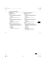
Dipswitch settings
1
Set the 10th bit of SW6 to ON.
2
Set SW4 as shown in the table below to select the
setting item No.974.
(The setting item No. will be displayed on LED1.)
3
Press SWP3 for two seconds or longer to change the
settings. (The settings can be checked on LED3.)
*1 Set SW4 while the unit is stopped.
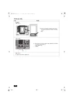
<A> Attach the supplied wiring diagram nameplate under the
caution plate on the main control box cover.
A
Label
<A> Bundle the excess panel heater wirings at the bottom of
the main control box with the cable tie.
A
Panel heater wiring
B
Cable tie
Re-place all components as they were.
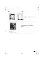
<A> Attach the supplied wiring diagram nameplate under the
caution plate on the control box front cover.
A
Label
<A> Bundle the excess panel heater wirings with the cable
strap for holding strong electrical wiring at the side of
the control box.
A
Panel heater wiring
B
Cable strap
Re-place all components as they were.
WT08867X01.book 38 ページ 2018年1月22日 月曜日 午後3時17分

