21
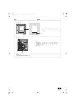
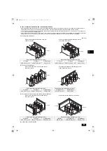
Step 2. Wiring the panel heater to the control box
9
9.2.0
<A>
A
B
S-module
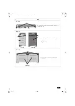
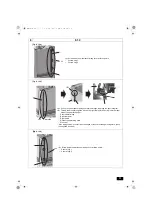
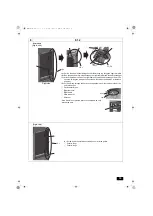
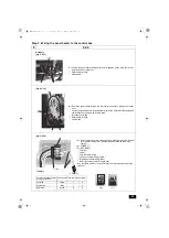
<A> Fasten the panel heater wirings with the wire saddles on the main control box
and the inverter control box.
A
Panel heater wirings
B
Wire saddle
[Fig. 9.2.0.1]
C
B
A
<A>
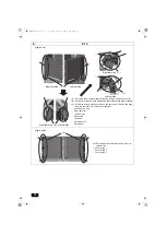
[Fig. 9.2.0.2]
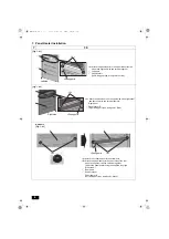
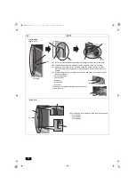
<A> Route the panel heater wirings into the inverter control box through the rubber
bush.
Fasten the panel heater wirings together with the fan motor electrical wiring and
the terminal assy wiring with a cable strap.
A
Terminal assy wiring
B
Panel heater wirings
C
Cable strap
A
<A>
B
C
D E F
1
2
3
4
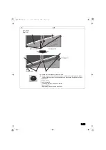
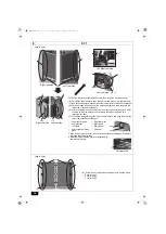
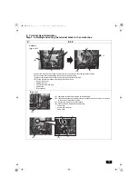
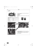
[Fig. 9.2.0.3]
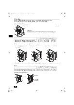
Location of panel heater
wiring connection
Wiring color Terminal block number
Left side
Yellow
1
4
Right side
Blue
1
4
Rear side
White
2
3
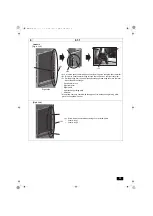
<A> Wire the panel heater wirings as shown in the figure. Match the label
color with the wiring color, and the label number with the wiring
number.
<B> CORRECT
<C> INCORRECT
A
Terminal
B
Label
C
Terminal assy wiring
D
Left panel heater wiring (yellow)
E
Right panel heater wiring (blue)
F
Rear right panel heater wiring (white)
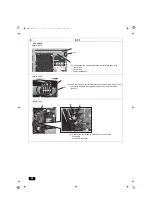
* See the figure below for how to connect two ring terminals to a single
terminal.
<C>
<B>
<Heater>
<CN510>
WT08867X01.book 21 ページ 2018年1月22日 月曜日 午後3時17分

