19
9. Terminal Assy Installation
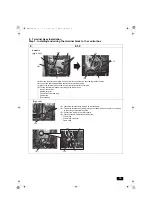
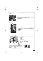
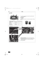
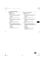
Step 1. Installing and wiring the terminal block to the control box
9
9.1.0
<A>
<C>
<B>
<A>
<C>
<D>
A
C
D
B
E
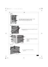
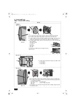
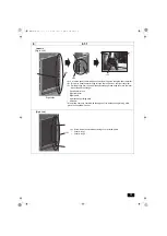
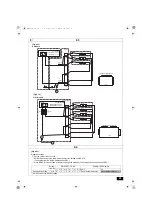
[Fig. 9.1.0.1]
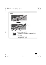
<A> Remove the attachment plate from the inverter control box by unscrewing the four screws.
<B> Loosen the cable strap holding the fan motor electrical wiring.
<C> Mount the terminal assy on the inverter control box with four screws.
<D> Thread the terminal assy wiring through the rubber bush.
A
Inverter control box
B
Attachment plate
C
Fan motor electrical wiring
D
Cable strap
E
Terminal assy
S-module
<A>
<B>
<D>
<C>
A
B
C
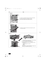
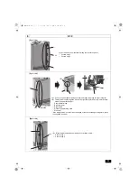
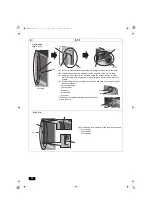
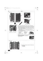
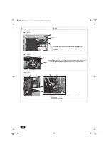
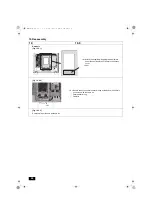
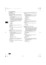
[Fig. 9.1.0.2]
<A> Fasten the terminal assy wiring with a wire saddle.
<B> Thread the terminal assy wiring through the rubber bush on the main control box
on the strong electrical wiring side.
<C> Connect the wiring to the circuit board.
<D> Fasten excess wiring with the cable strap.
A
Fuse wiring
B
Fuse wiring connector
C
Cable strap
WT08867X01.book 19 ページ 2018年1月22日 月曜日 午後3時17分

