2
6. Installation Procedures
6
6.0
<B>
<A>
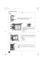
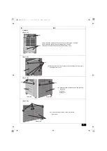
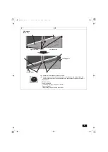
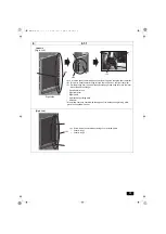
[Fig. 6.0.1]
<A> Remove the front panel from the unit by unscrewing the eight screws.
<B> Remove the fan guard by unscrewing the six screws.
* Remove the snow protection hood (optional parts), if any.
S-module
B
<B>
A
<A>
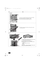
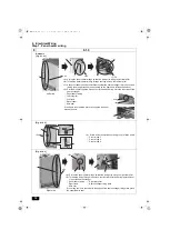
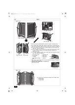
[Fig. 6.0.2]
B
A
C
<B>
<A> Remove the drain pan cover by unscrewing the screws and
cutting the cable tie.
<B> Remove the front drain pan by unscrewing the two screws.
Be sure to remove the two rod holders holding the check
joints to the drain pan.
A
Drain pan cover
B
Drain pan
C
Rod holder
B
D
C
A
<A>
<B>
<A>
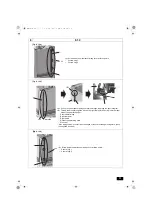
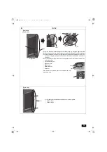
<A> Remove the top attachment and the bottom attachment connecting
the main control box and inverter control box by unscrewing the two
screws.
<B> Remove the cover from main control box by unscrewing the three
screws.
A
Top attachment
B
Bottom attachment
C
Main control box
D
Inverter control box
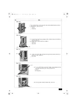
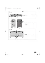
[Fig. 6.0.3]
A
A
B
B
<A>
<B>
<B>
<C>
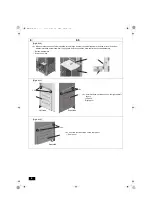
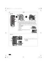
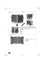
[Fig. 6.0.4]
<A> Cut the two cable ties holding the weak electrical wiring inside the main control box
in place.
<B> Loosen the four cable straps holding the weak and strong electrical wirings.
<C> Cut the two cable ties holding the rubber bush at the bottom of the main control box.
A
Cable tie
B
Cable strap
WT08867X01.book 2 ページ 2018年1月22日 月曜日 午後3時17分

