


5-3
Before taking a phenomenon as a trouble
5
In
Case of T
ro
uble
If image quality declines
Corrective measures against troubles in the case where satisfactory image quality is not provided are described
in this station.
Take measures in accordance with actual state of the picture.
If the measures fail restore the device to the normal state, contact your local MIMAKI distributor or MIMAKI office
call for service.
Resolving nozzle clogging
If nozzle clogging is not resolved even the head cleaning operation of P.2-8 has been executed, check the
following 2 items.
Fill ink with the operation of P.4-26.
Replace ink with the operation of P.4-3.
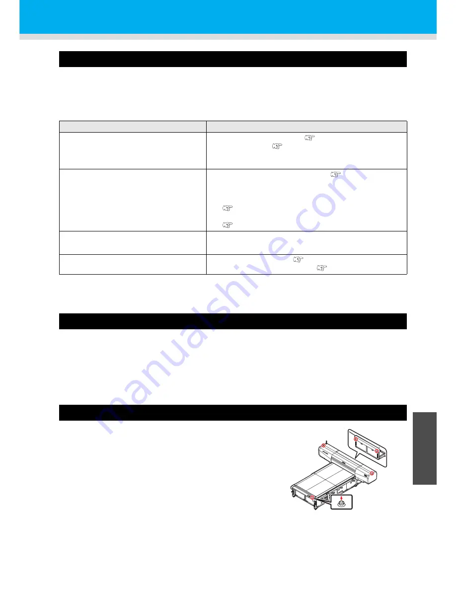
Stopping the unit during the operation
Press the EMERGENCY SWITCH for stopping the unit urgently for
the safety reason.
One EMERGENCY switch is placed on the front face of the unit and
2 are placed on each of the buck surface and Y-bar respectively.
Development
Corrective measure
Lines/thin spots are obvious occur
(1)
Execute the head cleaning. (
P.2-8)
(2)
Clean the wiper. (
P.4-12)
(3)
If slip of paper is present in the head path, for example, above
the work plate, remove it.
Large ink drop on media
(1)
Execute the head cleaning [normal]. (
P.2-8)
(2)
Dust the media.
(3)
Dust the table.
(4)
Execute the cleaning for the undersurface of the carriage.
(
P.4-8)
(5)
Set a correct value to the head gap value.
(
P.3-6)
Media is raised during printing and
printing stops.
*1
*1. During printing, media may be raised due to the heat from the UV LED, causing printing to be stopped.
(1)
Set new media and start printing.
A great deal of nozzle missing occurs.
(1)
Perform head cleaning. (
P.2-8)
(2)
Perform sub tank maintenance. (
P.4-15)
Summary of Contents for JFX-1631/1615 Plus
Page 1: ...MIMAKI ENGINEERING CO LTD URL http eng mimaki co jp D202017 20...
Page 82: ...3 38...
Page 122: ...4 40...
Page 134: ...5 12...
Page 138: ...6 4...
Page 152: ...6 18...
Page 153: ...D202017 20 25122014...


