background image

6-17

Maintaining the Capping Station

6

6

Mai
n

tenanc

e

Executes the NOZZLE PROTECT function automatically

You can set the status to enter the nozzle protection automatically (auto-execute function of NOZZLE PROTECT)
in case the device is not used for a certain amount of time.
In the nozzle protection status, NOZZLE PROTECT can be automatically executed regularly.

To use the auto-execute function of NOZZLE PROTECT, set the following items.

On Time

: Time from the stop of the device to the start of the nozzle protection status. 

Interval

: Execution interval of NOZZLE PROTECT in the nozzle protection status.

1

Press the 

 key in LOCAL to select the

printing mode.

2

Select [AutoNZL.PROTECT] of the maintenance menu.

(1)

Press the 

 key.

(2)

Press 

 to select [MAINTENANCE] and press the 

 key.

(3)

Press 

 to select [AutoNZL.PROTECT] .

3

Press the 

 key.

4

Press 

 to select [ON Time].

• The machine not being used means that it is in the standby status or the status that the power supply

switch under the operation panel is OFF (the sleep status).

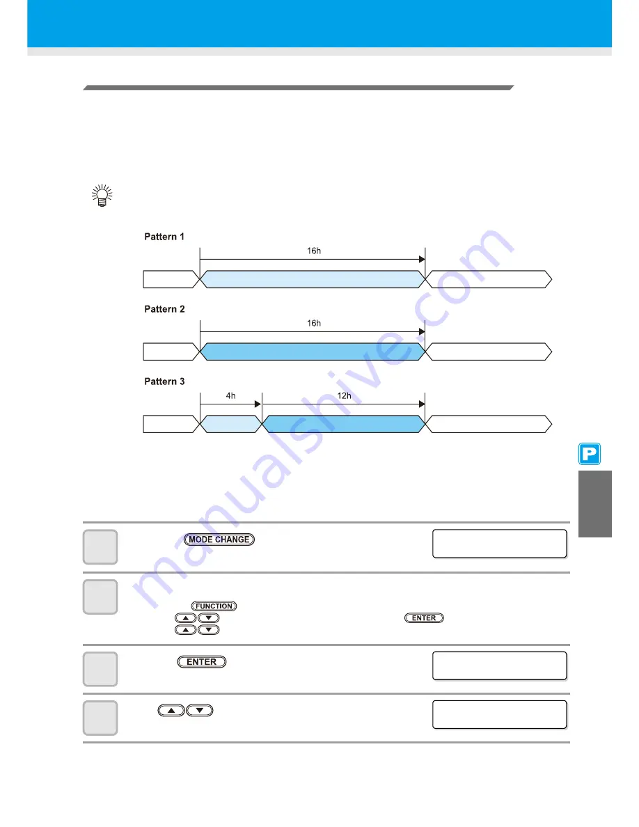
• The followings are the examples (three patterns) if you set the time length until the NOZZLE PROTECT

function is executed to “16h”.

In the nozzle protection status *2

In use

On standby *1

Executing NOZZLE PROTECT

In use

In sleep status *1

In use

On standby *1

Power switch OFF

In sleep status *1

Power switch OFF

*1 : If the time length set in P.4-31 “Setting Routine operations” and P.4-28 “Preventing nozzle clogging 

while power-off” has passed, maintenance operation is executed automatically.

*2 : In the nozzle protection status, a maintenance function set at P.4-28 “Preventing nozzle clogging while 

power-off” does not work.
After entering the nozzle protection status, this machine automatically performs NOZZLE PROTECT 
regularly.

Executing NOZZLE PROTECT

Executing NOZZLE PROTECT

In the nozzle protection status *2

In the nozzle protection status *2

< LOCA L . 1 >

[ # 0 1 ]

WI DTH : * * * * mm

A u t o NZ L . PROT ECT

ON T i me

< e n t >

A u t o NZ L . PROT ECT

ON T i me

< e n t >

Summary of Contents for CJV30-100BS

Page 1: ...MIMAKI ENGINEERING CO LTD URL http www mimaki co jp D201979 13...

Page 2: ...7 Media Sensor 1 7 Carriage 1 8 Capping Station 1 9 Pinch Rollers and Grid Rollers 1 9 Pen line Rubber 1 10 Media 1 11 Usable Sizes of Media 1 11 Caution in Handling of Media 1 11 Connecting Cables 1...

Page 3: ...m 2 25 Take up Device 2 29 Setting a Leaf Medium 2 31 When Changing the Origin 2 33 Test Printing 2 35 Test Printing 2 35 Performing Head Cleaning 2 36 Test Cutting 2 37 Preparing for the Heaters 2 38...

Page 4: ...erature Does Not Reach the Preset One 3 15 Setting the Printing Method 3 16 Setting of Printing Quality 3 16 Setting a Scanning Direction 3 18 Setting Logical Seek 3 19 Setting Drying Time 3 20 Settin...

Page 5: ...Cutting 4 22 Dividing and Cutting 4 23 Setting the Dividing and Cutting Function 4 23 Cutting Data by Using the Dividing and Cutting Function 4 25 Cutting with a Dotted Line 4 26 Changing the Order of...

Page 6: ...d Register Mark Sensor 6 4 Cleaning the Medium Holder 6 4 Maintaining the Capping Station 6 5 Cleaning the Wiper and Cap 6 6 Replacing the Wiper 6 8 Before Washing the Ink Discharge Passage 6 9 Cleani...

Page 7: ...y of Media Residual 6 37 If a Waste Ink Tank Confirmation Message Appears 6 39 Replacing the Cutter Blade 6 43 Replacing the Pinch Rollers 6 45 Replacing a Cutter Blade Not Included in the Accessories...

Page 8: ...ate radio frequency energy and if not installed and used in accordance with the Operation manual may cause harmful interference to radio communications Operation of this equipment in a residential are...

Page 9: ...s also necessary to keep this Operation manual on hand Make arrangements so that this manual is certainly delivered to the person in charge of the operation of this machine This Operation manual has b...

Page 10: ...erate the machine properly Useful information is given with this symbol Refer to the information to operate the machine properly Indicates the reference page for related contents The symbol indicates...

Page 11: ...oke or strange smell can result in fire or electric shocks If such an abnormality is found be sure to turn off the power switch immediately and unplug the cable from the wall outlet Check first that t...

Page 12: ...ere there is no steps When the machine is to be moved to any place other than on the same step free floor contact your distributor or a sales office of MIMAKI The ink contains organic solvent If ink h...

Page 13: ...ure to meet the characteristics of the media Set the temperature of the Pre heater Print heater and Post heater according to the type and characteristics of the media used Automatic temperature settin...

Page 14: ...clined surface A place where the temperature or humidity changes significantly Use the machine under the following environmental conditions Operating environment 20 to 35 C 35 to 65 Rh A place that vi...

Page 15: ...xiv How to Read this Manual...

Page 16: ...xv...

Page 17: ...s and Functions 1 4 Front Side of the Machine 1 4 Rear Sides 1 5 Operation Panel 1 6 Heater 1 7 Media Sensor 1 7 Carriage 1 8 Capping Station 1 9 Pinch Rollers and Grid Rollers 1 9 Pen line Rubber 1 1...

Page 18: ...nvironment of 20 to 35 C to ensure reliable printing The heater temperature may not reach the set value depending on the ambient temperature Model Width Depth Height Gross weight CJV30 60BS 1 524 mm 7...

Page 19: ...Do not push the cover to move this machine since the cover may be broken 3 Lock the casters When the machine is moved to any place other than on the same step free floor contact your distributor or o...

Page 20: ...ance cover Open the cover when carrying out maintenance Even when the power switch is OFF keep the cover closed Platen The printed media is printed out sliding on the platen Three heaters are installe...

Page 21: ...d left ends of the core of the roll media Roll holders are available for the 2 inches and 3 inches core of the roll media Clamp lever rear Interlocks with the clamp lever in the front of this machine...

Page 22: ...OTE key Registers the last input value as the setting value or goes to the immediate lower level of the hierarchy key Use this key to check the prints for errors in print mode and cut mode key Use thi...

Page 23: ...laten is very hot When the front cover Optional is to be opened or media is to be replaced lower the heater temperatures and wait until the platen temperature drops otherwise you can get burned When t...

Page 24: ...the conjunct unit to the printer unit with the cutter unit placed on the platen the movement speed of the first 20cm becomes slow to avoid injury from the cutter unit Height adjusting lever A height...

Page 25: ...etains the media with the pinch rollers and the grid rollers Be sure to wear the attached goggles in cleaning within the capping station to protect your eyes against ink Do not switch manually the pre...

Page 26: ...er 2 Install the pen line sponge 1 Align the right end of the pen line sponge with the right end of the platen 2 Install the pen line sponge Be careful of the following when installing the pen line ru...

Page 27: ...pe or weak glue for easy removal Use media recommended by MIMAKI Such media ensures reliable and high quality printing Set the heater temperature to meet the characteristics of the media Set the tempe...

Page 28: ...wly connected USB port use USB 2 0 repeater cables available on the market z Notes on peripheral devices in USB high speed mode When a peripheral device USB memory or USB HDD to be operated in USB hig...

Page 29: ...isk before outputting it for printing Connecting the Power Cable 1 Insert the power cable into an inlet of the machine 2 Secure a cable band Secure the cable with the cable band attached to this machi...

Page 30: ...en INK END or NEAR END is displayed on the display z When INK END is displayed 1 Pull out the ink cartridge to be replaced 2 Replace with a new ink pack and a new IC chip See the label attached on the...

Page 31: ...uine ink cartridges for this machine This machine functions by recognizing the genuine ink cartridges In case of trouble caused by modified ink cartridges or the like it shall be out of the warranty e...

Page 32: ...he computer However it does not perform printing or cutting Function To set Function mode press the key when this machine is in Local mode In this mode printing conditions can be set REMOTE The receiv...

Page 33: ...djusting the Position of the Pinch Roller According to the State of a Medium 2 17 Roll Stopper 2 22 Maximum Print Area Cut Area 2 23 Notes When Using Medium Holder 2 24 Setting a Roll Medium 2 25 Take...

Page 34: ...n also select one by pressing the key 4 Press the key For Selecting a User Type without Using You can select a user type by using the key in the printer mode without pressing the key Settings Referenc...

Page 35: ...lanation CUT1 to CUT3 This is a tool condition when a cutter is used PEN This is a tool condition when the pen is used HALF This is a tool condition when dotted line cutting is performed Press to sele...

Page 36: ...o PRS To return to the previous setting item press the jog key 6 Press to set a pressure value Set value 10 to 20 g The value can be set by the unit of 2 g 20 to 100 g The value can be set by the unit...

Page 37: ...d When the PRESSURE value is set at less than 20 g in Step 7 the speed value in Step 5 needs to be set at 10 cm s or less Otherwise the tool floats and this causes letters to be blurred and cutting re...

Page 38: ...leration speed displayed in the upper part of the display will not be renewed L 5 Press the key The set value will be registered z Relationships between cutting speed and acceleration speed If you set...

Page 39: ...the power ON Setting media Test cutting Refer to P 2 8 Turning the Power ON OFF Refer to P 2 37 Refer to P 2 10 Installing Tools Refer to P 2 15 Setting a Medium Refer to P 2 2 User Type for Printing...

Page 40: ...ower switch turned OFF when the main power switch is turned ON the power switch blinks in green 1 Turn the main power switch ON Set the main power switch located on the side of this machine to the I s...

Page 41: ...main power switch OFF When the main power switch is ON the power periodically turns ON and the nozzle clogging prevention function flushing function operates When the main power switch has been turned...

Page 42: ...2 Loosen the locknut and remove the adjustment knob from the holder 3 Insert a cutter blade in the hole of the adjustment knob Pick up the cutter blade with tweezers 4 Tighten the locknut Do not touch...

Page 43: ...e cutter may cut the backing paper through and damage the machine For the blade edge adjustment of cutters other than ones supplied with this machine see the Appendix P 6 46 Locknut Adjustment knob De...

Page 44: ...er 2 Fix the cutter holder Rotate the knob of the tool holder clockwise and fix the tool firmly Insert the cutter holder firmly so that there is no space under the holder Fix the cutter holder firmly...

Page 45: ...the position where you can assure easy access and then replace the blade edge 8 See P 2 12 Installing the Cutter Holder to replace the cutter holder When exchanging the cutter blade refer to P 2 10 M...

Page 46: ...ing screw does not touch anything 6 Fix the tool Turn the knob of the tool holder clockwise and fix the tool firmly When you use a ballpoint pen sold on the market use one with a diameter of 8 to 9 mm...

Page 47: ...sition of the lever referring to For the Adjusting Lever and the Range Set the height adjusting lever to the highest stage or the lowest stage Setting it to the intermediate height a printing fault ca...

Page 48: ...justing lever Head height Switching area Thin 2 mm The set position before shipping Switch by user Thick 3 mm Set the lever to Thick when a thicker medium such as tarpaulin or FF is used Set the lever...

Page 49: ...ing The pinch roller should be above the grid roller How to Adjust the Pinch Roller Move the pinch roller unit to adjust the position of the pinch roller Use the pinch roller guide mark for positionin...

Page 50: ...ill remain uncut when cutting the medium 1577 1620mm 1577 1620mm 1446 1514mm 1446 1514mm 1212 1272mm 1212 1272mm 1032 1092mm 1032 1092mm 732 792mm 732 792mm 576 644mm 576 644mm 364 424mm 364 424mm 241...

Page 51: ...um right end If adjusting them to the further position it will remain uncut when cutting the medium 1328 1371mm 1328 1371mm 1212 1272mm 1212 1272mm 1032 1092mm 1032 1092mm 732 792mm 732 792mm 576 644m...

Page 52: ...dium left end and 2cm from medium right end If adjusting them to the further position it will remain uncut when cutting the medium 973 1030mm 973 1030mm 900 960mm 900 960mm 732 792mm 732 792mm 576 644...

Page 53: ...two or more pinch roller units Adjust the pinch roller of both ends so that they are within the range of 10cm from medium left end and 2cm from medium right end If adjusting them to the further positi...

Page 54: ...e roll stopper In this case follow the steps below to lock the roll stopper 1 Pull the roll stopper in the direction shown right 2 Press the lock pin to hold the roll stopper The roll stopper works wi...

Page 55: ...610 mm The recommended dead space in the front end is 40 mm or more Turn the expand function OFF P 5 6 If the dead space in the front end is too small the media may become loose This affects print or...

Page 56: ...Exceed the Slit Line on the Platen If the medium is set with its end exceeding the slit line on the platen the medium may be lifted when it is fed obliquely This may cause damage to the head Set the...

Page 57: ...achine P 2 18 to P 2 21 Check that the roll stopper is not caught between the roll stopper arm and this machine If the roll stopper arm and the roll stopper are interlocked and they don t move enable...

Page 58: ...medium will be surely held when changing the medium size 8 Insert the roll medium in this machine The roll medium can be smoothly inserted by slanting the medium 1 Pull the medium out of the roll to t...

Page 59: ...ing clip lightly the medium with the medium holder When using a thick medium remove the medium holder from the medium before printing When setting the medium holder refer to P 2 24 You do not need to...

Page 60: ...t there is no slack or wrinkle on the medium by pulling it to the right and left evenly and then fix it with a piece of tape Once a printing condition or a cutting condition appropriate to the media i...

Page 61: ...justing the switch The take up direction of the medium is selectable by using the switch of the take up device Lever in top position REVERSE The take up device winds the medium with the printed side f...

Page 62: ...too weak The medium cannot be taken up firmly When the torque limiter is adjusted too strong Slack may occur depending on the medium and have an influence on the image quality In addition when perform...

Page 63: ...e section applicable to your machine P 2 18 to P 2 21 3 For printing clip lightly the medium with the medium holder When using a thick medium remove the medium holder from the medium before printing W...

Page 64: ...n or a cutting condition appropriate to the media is registered when setting the type and the tool condition setting the pinch roller on Step 5 to 7 is not needed When performing the settings for the...

Page 65: ...ter unit as a reference When changing the origin position in the cutter unit use the tool holder pen point of the cutter unit as a reference To print with the cross direction Y direction aligned with...

Page 66: ...left end of the first pinch roller the right end pinch roller seen from the front of the main body The value in the scanning direction Y can be changed using Margin P 5 8 in Function mode This can be...

Page 67: ...bnormal perform head cleaning P 2 36 When using a leaf medium set one that is larger than an A4 size medium in the longitudinal direction When using a roll medium rewind the medium by hand before prin...

Page 68: ...normal When 600cc cartridge is used Q Even when Ink Level is displayed enough ink for head cleaning may remain in the ink pack When Ink Level appears see When Ink Level is displayed in the provided ma...

Page 69: ...e press the key to switch the setting of pinch roller pressure to the cut mode and then perform the test cutting If the key is pressed switching operation will not be performed When the settings for t...

Page 70: ...ress the key to stop heating The screen returns to Local You can register the temperature of the heaters beforehand according to the types of media you use P 3 2 Registering All Printing Conditions To...

Page 71: ...e Glossy chloroethylene Tarpaulin FF Pre heater setting 35 C 35 C 35 C Print heater setting 35 C 35 C 35 C Post heater setting 50 C 50 C 50 C Adjust the temperature appropriately according the state o...

Page 72: ...of the set medium or the position of the print origin even when the same data is printed This is because of a difference in resolution When using a roll medium rewind the medium by hand before printin...

Page 73: ...data sending at the PC side during the data is sent from the PC Printing restarts from the interrupted data by repressing the key Deleting Received Data Data Clear When you want to stop printing dele...

Page 74: ...e is operating The operation of the machine stops in a while and it enters a local state The time it takes for the operation of the machine to stop is different depending on the data being processed W...

Page 75: ...Cutter Unit Temporarily When cutting or printing with a pen job is finished the cutter unit is on the platen To check the result of cutting printing with a pen or to set a new medium follow the steps...

Page 76: ...n a medium is cut be careful that the printed side does not touch the floor or the printed side of other already cut media When you use a take up device roll up the cut medium by using the switch of t...

Page 77: ...14 When the Heater Temperature Does Not Reach the Preset One 3 15 Setting the Printing Method 3 16 Setting of Printing Quality 3 16 Setting a Scanning Direction 3 18 Setting Logical Seek 3 19 Setting...

Page 78: ...e user type to another Example of Type Registration How to Register User Types 1 Press the key in LOCAL to select the printing mode 2 Press the key 3 Press the key 4 Press to select one of the types 1...

Page 79: ...to 90 min by the unit of 10 min OFF TIME NONE 0 to 90 min by the unit of 10 min PRINT MODE P 3 16 DRAFT QUALITY STD FAST FINE Used to set printing quality and a printing direction FINE QUALITY STD FAS...

Page 80: ...nting method Ink laying printing Drying time Automatic Cutting Pre feed Color pattern Refreshing VACUUM Feeding speed level AUTO CLEANING P 3 24 ON INTERVAL 10 to 1 000 to 10 000 mm Used to set the au...

Page 81: ...rollers other than those at both ends of the medium according to usage MIDDLE LOW OFF No 2 to 7 1 1 The number of pinch rollers varies according to the machine type Set the number of the leftmost pinc...

Page 82: ...key 5 Press the key 6 Press to set the pressure for the pinch rollers at both ends of the medium Set value HIGH MID LOW 7 Press to move the cursor to the middle pinch roller setting End pinch roller l...

Page 83: ...s the key 3 Press to select a pinch roller to set and press to set the advanced setting 4 Press the key 5 Press the key several times to end the setting Pinch roller pressure set here is reflected to...

Page 84: ...ve changed the temperature of the heaters make sure that the CONSTANT lamp lights up and that the preset temperature is reached and then start the correction When printing with a take up device set th...

Page 85: ...ing A media feeding rate can be corrected even in the remote mode or when image data is printed 1 Press the key in the remote mode 2 Press the key 3 Press to enter a corrected feeding rate Corrected f...

Page 86: ...he key 8 Press the key to start pattern printing Multiple test patterns are printed The printed patterns are called Pattern 1 Pattern 2 Pattern 3 in the order of printing When detecting the medium and...

Page 87: ...he correction value in not between 40 and 40 adjust the height of the printing heads and then perform the operations in Step 2 and later 2 types of the correction value is available depending on the h...

Page 88: ...eaters falls to reach the preheat temperature after printing has been complete Set value NONE 0 to 90 min by the unit of 10 min The preheat temperature has been preset and cannot be changed If the mac...

Page 89: ...Item selection Select one with Time setting Set time with 12 Press the key 13 Press the key several times to end the setting The screen returns to LOCAL Use this machine at a temperature between 20 t...

Page 90: ...dry increase the heater temperature so that the ink fixing and drying characteristics can be improved Check the items in the following method to set an appropriate temperature Wait until the CONSTANT...

Page 91: ...the vicinity of 100 magenta area shows that media feeding has been adjusted appropriately In the blue area 100 magenta 100 cyan however speckled patterns and banding have occurred This banding is a re...

Page 92: ...printing mode 2 Press the key 3 Press the key 4 Press to select one of the types 1 to 4 and press the key 5 Press to select PRINT MODE 6 Press the key 7 Select items to set 1 Press to select DRAFT QU...

Page 93: ...t the number of passes 11 Press the key several times to end the setting Combination of Factors That Can Be Set When changing the details of printing quality in Steps 9 and 10 of Setting of Printing Q...

Page 94: ...w Bi D Printing is performed in both outward and return directions of the printer unit Select this when you want to print in a shorter period of time Uni D Printing is performed only in the outward di...

Page 95: ...nt in a shorter period of time OFF The printer unit moves from the right edge to the left edge of a medium regardless of the size of the data When you use a medium on which ink is hard to dry you can...

Page 96: ...Overview SCAN 0 0 to 19 9 sec Ink drying time for each scanning is set During bidirectional printing the machine stops for a certain period of time specified for each of the outward and return scanni...

Page 97: ...Setting Drying Time 3 21 3 Extended Functions Printer 8 Press the key 9 Press the key several times to end the setting 1 DRY I NG T I ME e n t...

Page 98: ...g ALL HOST or ALL PANEL press the key and proceed to Step 12 8 Press the key The setting screen of media correction appears 9 Press to select HOST or PANEL 10 Press the key You can move between items...

Page 99: ...Perform the same operations as in Steps 9 and 10 to set other items 12 Press the key several times to end the setting Even with the setting by the host being prioritized the items set by the panel be...

Page 100: ...y in LOCAL to select the printing mode 2 Press the key 3 Press the key 4 Press to select one of the types 1 to 4 and press the key 5 Press to select AUTO CLEANING 6 Press the key 7 Press to select ON...

Page 101: ...veral times to end the setting This function does not operate when ink near end occurs See P 1 14 Changing an Ink Cartridge to solve ink near end Depending on the state of the heads etc the image qual...

Page 102: ...ect one with Setting of an interval and type Set an interval and type with 10 Press the key Press the key several times to end the setting Set Item Set Value Overview INTERVAL 10 to 1 000 mm Interval...

Page 103: ...Press to select one of the types 1 to 4 and press the key 5 Press to select an item to set See List of Settings P 3 28 6 Press the key 7 Press to select a set value See List of Settings P 3 28 8 Pres...

Page 104: ...s set AUTO CUT Whether a medium is automatically cut after printing is set ON OFF PRE FEED Whether a medium is fed back and forth before printing is set ON OFF COLOR PATTERN It is set whether a color...

Page 105: ...s 1 to 4 and press the key 5 Press to select SETUP COPY 6 Press the key 7 Press to select the type to copy 1 to 4 or ALL If ALL is selected the set contents of all types are same 8 Press the key 9 Pre...

Page 106: ...rinting mode 2 Press the key 3 Press the key 4 Press to select one of the types 1 to 4 and press the key 5 Press to select SETUP RESET 6 Press the key 7 Press the key The already configured settings a...

Page 107: ...The present operating state of the exhaust fan is switched P 3 31 DRYNESS FEED ON OFF It is set whether a medium is fed for it to be dried after printing has been completed P 3 32 STAMP SETUP ON OFF...

Page 108: ...edium is fed for it to be dried after printing has been completed 1 Press the key in LOCAL to select the printing mode 2 Press the key 3 Press to select MACHINE SETUP 4 Press the key 5 Press to select...

Page 109: ...to select the printing mode 2 Press the key 3 Press to select MACHINE SETUP 4 Press the key 5 Press to select STAMP SETUP 6 Press the key 7 Press to select ON OFF 8 Press the key Press the key severa...

Page 110: ...select a set value FEED DIR Oriented in the media feeding direction rear default setting SCAN DIR Oriented in the media scanning direction lateral 8 Press the key Press the key several times to end t...

Page 111: ...manual 600 cc Ink Pack Ink Chip 1 1 Attached to the 600cc ink pack Scale To calculate the remaining ink quantity input the weight of the eco case and the 600 cc cartridge into this machine Use a scal...

Page 112: ...ink station Mount the 600 cc ink pack and the ink chip on the eco case and set it to the ink slot The input screen for the weight of the eco case will be displayed 3 Pressing the keys input the weigh...

Page 113: ...Slot by pressing the keys The selected slot is highlighted 8 Press the key The weight input screen is displayed 9 Pressing the keys input the weight of the eco case Press the keys to move to another...

Page 114: ...tely weigh the 600 cc cartridge down to 1 gram unit If available ink remains Ink Level warning disappears and NEAR END appears If Ink Level warning is displayed after inputting the weight available in...

Page 115: ...he eco case including the 600 cc ink pack 3 Reinsert the 600cc cartridge 4 Pressing the keys input the weight of the 600cc cartridge Press the keys to move to another digit Press the keys to input the...

Page 116: ...the 600cc cartridge and follow the procedures from the Step 3 again Error when performing maintenance function When performing the maintenance function such as the head cleaning or the ink filling for...

Page 117: ...manual 600 cc Ink Pack Ink Chip 1 1 Attached to the 600cc ink pack Scale To calculate the remaining ink quantity input the weight of the eco case and the 600 cc cartridge into this machine Use a scal...

Page 118: ...ink station Mount the 600 cc ink pack and the ink chip on the eco case and set it to the ink slot The input screen for the weight of the eco case will be displayed 3 Pressing the keys input the weigh...

Page 119: ...Slot by pressing the keys The selected slot is highlighted 8 Press the key The weight input screen is displayed 9 Pressing the keys input the weight of the eco case Press the keys to move to another...

Page 120: ...by resetting the 600 cc cartridge indicating Ink Level warning in the local mode or remote mode during waiting or printing Weight the cartridge exactly down to the gram Entering a larger weight than...

Page 121: ...n P 5 14 When an error occur in the Step 6 This function stores the calculated quantity of remaining ink in the ink chip of the 600cc cartridge If the 600cc cartridge is removed or there is a problem...

Page 122: ...g ink in the ink chip of the 600cc cartridge If the 600cc cartridge is removed or there is a problem on the contact of this device and the ink chip the data storage in the ink chip cannot be performed...

Page 123: ...TEMP 6 Press the key 7 Press to select a set value Not wait ARR The error message is displayed for a moment and printing starts Wait arrival After the error message is displayed wait until the ambien...

Page 124: ...appears An ink cartridge that is once set YES for extension cannot be changed the setting To extend multiple inks expiry month at a time set the expired ink cartridges and then set the extension Exten...

Page 125: ...H or COMPLETELY EXPIRED appears on the display and the cartridge lamp lights in red A message Expiration 1MONTH appears on the display and the cartridge lamp blinks in red A message Expiration appears...

Page 126: ...LEVEL Low ink cartridge is used first EXP DATE Close to date ink cartridge is used first 8 Press the key 9 Press the key several times to end When expired ink cartridge is set the expired cartridge i...

Page 127: ...to be used first Press the key 4 Press the key It enters in the LOCAL or the REMOTE mode Usually when both an ink cartridge and the bulk ink system MBIS1 are set in the supply path of the same color...

Page 128: ...3 52...

Page 129: ...4 17 Setting Automatic Cutting 4 22 Dividing and Cutting 4 23 Setting the Dividing and Cutting Function 4 23 Cutting Data by Using the Dividing and Cutting Function 4 25 Cutting with a Dotted Line 4 2...

Page 130: ...o 7 1 1 The number of pinch rollers varies according to the machine type Set the number of the leftmost pinch roller according to the size of the medium to be used Set pressure Usage ENDS High INNER H...

Page 131: ...HALF PEN and press the key 5 Press the key twice 6 Press to set the pressure for the pinch rollers at both ends of the medium Set value HIGH MID LOW 7 Press to move the cursor to the middle pinch rol...

Page 132: ...P 4 3 Setting for the Pinch Rollers 2 Press the key 3 Press to select a pinch roller to set and press to set the advanced setting 4 Press the key 5 Press the key several times to end the setting The p...

Page 133: ...be omitted there is no need to set the TP4 In that case however cutting distortion will increase When the registration detection is set to OFF the machine doesn t enter registration mode P 4 11 If th...

Page 134: ...e at least 20 mm away from the front end of the medium The TP2 end position must be at least 30 mm away from the rear end of the medium Register mark Type 1 Register mark Type 2 The register mark desc...

Page 135: ...f Wrong Detection 1 There is a line outside the register marks Example of Cause of Wrong Detection 2 The distance between register marks TP2 and TP1 or TP4 and TP2 is smaller than the mark length for...

Page 136: ...Register Marks for Copied Designs For Type 1 register marks the distance between the marks must be not shorter than two times the mark length and not longer than 1 000 mm For Type 2 register marks th...

Page 137: ...x 297 mm to A3 size 297 mm x 420 mm If you follow this recommendation you can minimize wasteful spaces and arrange the designs efficiently Color of Mark The mark must be printed in black against the w...

Page 138: ...on of print cut with Raster Link Pro 4 SG or later be careful to the following items 1 When performing combined operation of print cut with the attached application software to this device Rasater Lin...

Page 139: ...p 7 proceed to Step 12 9 Press to select the following items and then press the key The following items are provided for the register mark detection setting Mark detect Register mark size offset Y off...

Page 140: ...ding and the width direction 4pt Detects the four register marks TP1 TP2 TP3 and TP4 Performs the skew correction the scale correction in both directions and the trapezium correction Set Value Descrip...

Page 141: ...e detecting register marks consecutively based on the first data For leaf sheets cut sheets the value of COPIES Y is used as the number of copies When the number of copies can be set on the applicatio...

Page 142: ...g register marks again with the following procedures If the coordinate value of B axis of the Register mark 1 is misaligned exceeding the setting value cutting operation suspends When pressing the key...

Page 143: ...eet is detected the display indicates that the cutter unit is waiting for the register mark detection operation 3 Move the Light Pointer into the area shown below by pressing If the medium is curled s...

Page 144: ...gain 5 Set the origin The display will show the available cutting area and then return to LOCAL Setting the Origin of the Register Mark after Test Cutting 1 Confirm the cutting mode is local press key...

Page 145: ...s P 4 6 The setting values are kept in memory even when the power is turned OFF The settings performed here for type and length of the register mark are reflected in the settings of Setting Register M...

Page 146: ...ster mark and then press the key Set value TYPE 1 TYPE 2 The value entered here is reflected in the MARK DETECT 10 Press to set the register mark reading speed and then press the key Set value 10 to 2...

Page 147: ...n the Y direction minus direction to confirm that the line can be detected 5 Confirm that the buzzer sounds 4 times upon completion of Steps 1 to 4 When the detection behavior completes successfully t...

Page 148: ...y to switch the mode to cutting mode 3 Press the key 4 Press to select MAINTENANCE 5 Press the key twice 6 Press to select POINTER OFFSET 7 Press the key A 10 mm by 10 mm cross pattern will be plotted...

Page 149: ...by pressing 3 Press the key 4 Press to select MAINTENANCE 5 Press the key twice 6 Select LEVEL ADJUST by pressing 7 Press the key 8 Press the key after the number displayed on the screen is stabilize...

Page 150: ...eed to Step 10 8 Press to select a margin length 0 to 30 mm and press the key 9 Press the key several times to return to LOCAL The setting configured here is not reflected in the automatic cutting dur...

Page 151: ...ss the key 7 Press to select ON and press the key When having selected OFF proceed to Step 11 The following convenient functions can be used with the dividing and cutting function Cutting a frame Alon...

Page 152: ...re During the operation of dividing and cutting data sent from the host computer is ignored Dividing and Cutting cannot be performed in any of the following cases When the data size is larger than the...

Page 153: ...rigin When there is no space to be cut replace the medium 5 Press the key to go to the remote mode The medium is fed by the maximum medium length of the cut data and cut When the medium is not fed or...

Page 154: ...the key 3 Press the key 4 Press to select the tool condition HALF and press the key 5 Press to select HALF CUT 6 Press the key 7 Press to select a cutting pressure for Half cutting Set value 0 to 300...

Page 155: ...line cannot be set The set values are recorded even when the power has been turned OFF When a medium is cut with a dotted line the medium is cut along with the backing sheet Therefore the life of a c...

Page 156: ...vement from a down stroke with a pen to an up stroke with a pen After one block has been cut a block whose starting point is closest to the already cut block is cut The starting point and cutting dire...

Page 157: ...s CUT1 to CUT3 PEN and HALF and press the key 5 Press to select SORTING 6 Press the key 7 Press to select ON 8 Press the key 9 Press to select AUTO FEED When performing AUTO FEED select ON 10 Press th...

Page 158: ...ORTING The set values are recorded even when the power has been turned OFF When the set value has been changed the data in the reception buffer is cleared When the sorting function is set to ON the re...

Page 159: ...mount of the cutting of the medium is not fed ERROR 15 C AUTO FEED is displayed After replacing the medium with a longer one perform data transmission or cut the data into pieces according to the spec...

Page 160: ...r is installed Set item Overview P C ORIGIN OFFSET Adjusts the misalignment between the print origin and the cutting origin P C SCALE ADJUST Adjusts the scale to apply cutting to the correction value...

Page 161: ...ttern and adjust the misalignment Press to enter an offset value of the cutting line approximately 0 05mm per 1 step Select X Y direction Press Enter an offset value Press 11 Press the key Perform the...

Page 162: ...emote status 3 Press the key 4 Adjust by pressing Change the direction of X Y with and enter the offset value with 5 Press the key to save the adjusting value When you save the adjusting value the val...

Page 163: ...n the Y direction but it has no effect on this adjustment 12 Press to set 13 Press the key The machine cuts from the pattern 1 to 9 14 Remove the pattern from 1 and select one that fits the cutting li...

Page 164: ...ns CUT1 to CUT3 PEN and HALF and press the key 5 Press to select an item to set See List of Settings to select one 6 Press the key 7 Press to select a set value See List of Settings to select one 8 Pr...

Page 165: ...5 10 20 30 DUMMY CUT P 4 38 The operation of dummy cutting is set OFF ON MEDIA TYPE 1 1 When setting the medium setting to HEAVY the cutting speed is limited to 20cm s The weight of a medium to be mou...

Page 166: ...racters About Cutter Blade Corrected Pressure Offset Some part of a medium is left uncut because the pressure applied when the cutter blade touches the medium is weak When an optional eccentric blade...

Page 167: ...g is performed with extra cutting space at the front by the specified amount of length at the start of cutting and tool up is performed at the end going too far With setting the over cutting properly...

Page 168: ...ss the key 7 Press to select the tool condition to copy CUT1 to CUT3 PEN HALF or ALL If ALL is selected the set contents of all tool conditions are same 8 Press the key 9 Press the key 10 Press the ke...

Page 169: ...CUT1 to CUT3 PEN and HALF and press the key 5 Press to select SETUP RESET 6 Press the key 7 Press the key The set items and parameters are initialized 8 Press the key several times to return to LOCAL...

Page 170: ...een performed data stored in the reception buffer is deleted When detecting the medium and the mode is in print mode if you perform the sample cut as it is the following screen will be displayed by pr...

Page 171: ...Sample Cutting When sample data can be cut normally but other data cannot be cut normally D The host computer has an abnormality When both sample data and other data cannot be cut normally D Increase...

Page 172: ...rview Cutting interval 10 to 10 000 mm Distance between the leading and terminal ends of a cut medium is set Leading end adjustment cutting 0 to 500 mm The length of a medium s leading end to be cut i...

Page 173: ...iple Pieces with a Certain Length 4 45 4 Extended Functions Cutting 11 Press the key Cut is performed for the specified number of times Pressing the key suspends the operation 12 Press the key several...

Page 174: ...ect the cutting mode 2 Set an origin Set the origin referring to P 2 33 3 Press the key 4 Press to select No COPIES 5 Press the key 6 Press to set the number of pieces of data 1 to 999 produced by cop...

Page 175: ...th themselves being overlapped While data is being cut into pieces according to a specified number data from the host computer cannot be received There must be an interval of 10 seconds or more betwee...

Page 176: ...to select the cutting mode 2 Press the key 3 Press to select MAINTENANCE 4 Press the key 5 Press to select STEP SIZE 6 Press the key 7 Press to select the setting value Setting value 0 01 or 0 025 8...

Page 177: ...s the key in LOCAL to select the cutting mode 2 Press the key 3 Press to input the feed amount Set value 0 1 m to 51 0 m by the unit of 0 1 m 4 Press the key The medium will be fed by the input length...

Page 178: ...Power off and CUT HEAD RETRUCT 2 Press the key The machine works depending on the setting selected on the step 1 Setting above keeps the heater OFF in the cutting mode If switched from the cutting mod...

Page 179: ...llers 5 3 Setting a Cut Method 5 4 Setting CONFIRM FEED 5 5 Setting the Expand Function 5 6 Setting Margins 5 8 Setting the RECEIVED DATA 5 9 Setting Time 5 10 Setting Units 5 11 Setting the MACHINE N...

Page 180: ...RGIN P 5 8 LEFT 0 to 85mm by the unit of 1 mm Used to set margins on the right and left edges of a medium RIGHT 0 to 85mm by the unit of 1 mm RECEIVED DATA P 5 9 AUTO MANUAL This setting can be change...

Page 181: ...pinch roller pressure need to be set each time the medium is set according to the width of the medium PWR ON ONLY The pinch roller number and the pinch roller pressure need to be set when the medium i...

Page 182: ...t a set value Set value 2 STEP 3 STEP 7 Press the key 8 Press the key several times to end the setting Set Value Overview 2 STEP The medium is cut in two steps 3 STEP The medium is cut in three steps...

Page 183: ...lect ON OFF ON To slightly take up the medium fed by the confirmation feeding function OFF Not to take up the medium 9 Press the key 10 Press the key several times to end the setting Set Value Overvie...

Page 184: ...Expand Function ON Expand function will be enabled after setting of the expand and the medium is detected 1 Press the key in LOCAL 2 Press to select COMMON SETUP 3 Press the key 4 Press to select EXPA...

Page 185: ...selecting OFF on Step 6 When you turn the Expand function ON a paper jam may occur if excessive pressure is applied to the medium When axis correction has not been performed the cutter blade can come...

Page 186: ...width of the margin with 7 Press the key 8 Press the key several times to end the setting Set Item Set Value Overview LEFT 0 to 85 mm The left margin of a medium to be printed or cut is set RIGHT 0 to...

Page 187: ...he received data MANUAL Set this parameter when executing printing cutting with the application other than those that come with the machine RasterLinkPro4 or later FineCut7 or later 1 In this case thi...

Page 188: ...uture time after the present one has been set by mistake performing the following operations in Step 7 enables the already set future time to be restored to the previously set time 1 Press the key in...

Page 189: ...Press the key 4 Press to select UNIT SETUP 5 Press the key 6 Press to select a unit Item selection Select one with Unit setting Enter with 7 Press the key 8 Press the key several times to end the set...

Page 190: ...elect COMMON SETUP 3 Press the key 4 Press to select MACHINE NAME 5 Press the key 6 Press to select a machine name 01 to 99 7 Press the key 8 Press the key several times to end the setting FUNCT I ON...

Page 191: ...EY BUZZER 5 Press the key 6 Press to select ON OFF 7 Press the key 8 Press the key several times to end the setting When the key buzzer is set to OFF the buzzer sound for errors warnings operation com...

Page 192: ...er of occurrence Maintenance history This displays the date and time when the maintenance function was used The maintenance history mainly describes the manual and automatic regular or sleep mode clea...

Page 193: ...is displayed Version Version information such as F W is displayed Printing mode history Resolution length of a printed medium etc are displayed The date year month day of printing is displayed Serial...

Page 194: ...are printed Cutting mode The settings in the cutting mode are printed Running meter A running meter is printed All All lists are printed When detecting the medium and the mode is in cut mode if you pe...

Page 195: ...hen Nozzle Clogging Cannot Be Solved 6 21 FILL UP INK 6 21 DISCHARGE WASH 6 22 Supplying the Machine with Ink Anew 6 24 Preventing Nozzle Clogging When the Power Is OFF 6 26 Setting the Refreshing Int...

Page 196: ...ble ink jetting it is necessary for the machine to eject a small amount of ink flushing regularly when a printing outputting operation has not been performed for a long time When the machine is not to...

Page 197: ...ith lint paper dust etc generated when a medium is cut Wipe off conspicuous stains with a soft hair brush a dry cloth a paper towel etc When the platen is stained with ink wipe it off with a paper tow...

Page 198: ...unit perform the operations on P 6 19 Cleaning the Ink Head and the Area around It Steps 1 and 2 and move the carriage to the left end Cleaning the Medium Holder When the medium holder is covered wit...

Page 199: ...y with ink dust etc If nozzle missing cannot be corrected even after head cleaning P 2 40 has been performed use a cleaning kit and clean stick Tools required for maintenance Kit of cleaning solution...

Page 200: ...the wiper Pull out the wiper by holding the protrusions at its both ends 6 Clean the wiper and bracket Wipe off the ink sticking to the wiper and bracket with a clean stick dipped in cleaning solution...

Page 201: ...per to its original position Insert the wiper by holding its both ends 9 Clean the cap rubber and wiper cover Wipe off the ink sticking to the cap rubber and wiper cover with a clean stick dipped in c...

Page 202: ...per by holding the protrusions at its both ends 7 Insert a new wiper Insert a new wiper by holding its both ends 8 Press the key After its initial operation the machine returns to LOCAL A cleaning wip...

Page 203: ...4 Press the key 5 Press the key When a normal cartridge has been set proceed to Step 7 6 Set a cartridge 7 Press the key The cartridge starts to be filled with cleaning solution When the following me...

Page 204: ...Press the key 3 Press to select Maint WashLiquid 4 Press the key 5 Press to select DISCHARGE 6 Press the key When the cartridge has been disengaged proceed to Step 8 7 Remove the cartridge 8 Press th...

Page 205: ...er and bracket with a clean stick dipped in cleaning solution for maintenance SPC 0369 3 Insert the wiper into the original position by holding the protrusions at its both ends 7 Press the key Check t...

Page 206: ...ected even after this cleaning has been performed several times perform When Nozzle Clogging Cannot Be Solved P 6 21 and DISCHARGE WASH P 6 22 When the problem is not solved even after the operation a...

Page 207: ...s dripping During the idle absorbing is interrupted repeat the drops several times to fill the cap with the cleaning solution just before the solution overflows from the cap 7 Press the key After the...

Page 208: ...dipped in cleaning solution for maintenance SPC 0369 3 Insert the wiper into the original position by holding the protrusions at its both ends Check the items on the right beforehand Is NEAR END or I...

Page 209: ...e washed When the nozzles have been completely washed the head moves onto the platen 12 Press the key and fill up the cap with cleaning solution for maintenance When you press the key cleaning solutio...

Page 210: ...filled fill it by referring to P 6 9 Filling the Pump Tube with Cleaning Solution for Maintenance Hasn t a warning occurred in the maintenance washing liquid cartridge If the warning message of Wash L...

Page 211: ...used means that it is in the standby status or the status that the power supply switch under the operation panel is OFF the sleep status The followings are the examples three patterns if you set the...

Page 212: ...rval number of days of NOZZLE PROTECT Set value OFF 1 to 14 days 11 Press the key Press the key several times to end If maintenance washing liquid has not been filled in the machine the screen on the...

Page 213: ...maintenance cover counterclockwise to remove them 2 Remove the maintenance cover 4 Press the key 5 Press the key Carriage will move to the left end of this device Tools needed for cleaning Clean stic...

Page 214: ...n completed press the key After its initial operation the machine returns to LOCAL Clean the area around the ink head about twice a week it varies depending on the frequency the machine is used Clean...

Page 215: ...nd the setting When 600cc cartridge is used Q Even when Ink Level is displayed enough ink for head cleaning may remain in the ink pack When Ink Level appears see When Ink Level is displayed in the pro...

Page 216: ...eaning solution remaining in the head or tube is discharged into the waste ink tank When the cleaning solution has been discharged completely the screen on the right appears To use this function the d...

Page 217: ...ning solution remaining in the head or tube is discharged into the waste ink tank When the cleaning solution has been discharged completely the screen on the right appears Check the state of the waste...

Page 218: ...owing BOOT 2 Check the ink type to fill and then press the key To check the state of the cartridge press the key P 7 5 3 Check the ink set the color to fill and then press the key You cannot change th...

Page 219: ...Step 5 When various ink errors including Almost no ink and No ink occur ink does not start to be supplied to the machine When ink does not start to be supplied to the machine in Step 5 1 Press the ke...

Page 220: ...n each refreshing operation is set PUMP TUBE WASH The interval between each PUMP tube washing operation is set CLEANING The interval between each cleaning operation is set Ink Type Refreshing PUMP Tub...

Page 221: ...nting mode 2 Select SLEEP SETUP of the maintenance menu 1 Press the key 2 Press to select MAINTENANCE and press the key 3 Press to select SLEEP SETUP 3 Press the key 4 Press the key 5 Press to set the...

Page 222: ...lue OFF or 1 to 168 hours 6 Press the key 7 Press the key several times to end the setting When the machine has not been filled with cleaning solution the screen on the right appears in Step 5 Fill th...

Page 223: ...2 Press to select MAINTENANCE and press the key 3 Press to select SLEEP SETUP 4 Press the key 3 Press to select CLEANING 4 Press the key 5 Press to set the interval between each cleaning operation Se...

Page 224: ...is wiped and dew condensation is removed REFRESH OFF 1 to 168 hours The interval between each refreshing operation is set PUMP TUBE WASH The interval between each PUMP tube washing operation is set C...

Page 225: ...In addition the larger the difference between the set temperature of the print heater and the ambient temperature is the more easily the evaporated solvent can condense 1 Press the key in LOCAL to se...

Page 226: ...r than the ambient temperature and the difference between the two exceeds a specified temperature the regular wiping function is activated 11 Press the key 12 Press the key several times to end the se...

Page 227: ...2 Press to select MAINTENANCE and press the key 3 Press to select ROUTINE SETUP 4 Press the key 3 Press to select REFRESH 4 Press the key 5 Press to set the interval between each refreshing operation...

Page 228: ...end the setting This function can be performed only when the states shown by the screens below are maintained When the machine has not been filled with cleaning solution the screen on the right appear...

Page 229: ...e key The cleaning type selection screen appears 7 Press to select a cleaning type Set value NORMAL SOFT HARD 8 Press the key 9 Press the key several times to end the setting This function is not perf...

Page 230: ...to select the printing mode 2 Select WIPER LEVEL of the maintenance menu 1 Press the key 2 Press to select MAINTENANCE and press the key 3 Press to select WIPER LEVEL 3 Press the key 4 Press to set a...

Page 231: ...of a medium is displayed in the remote mode However when a leaf medium is used the length of the medium to be printed is displayed When Remaining amount of a medium to display is set to OFF the remai...

Page 232: ...starts to be printed When the printing has been completed the screen returns to LOCAL Set Remaining amount of a medium to display to ON When you replace the medium you use now with another it is recom...

Page 233: ...k still has a capacity for waste ink 1 Press to select Continue The amount of discharged ink is not reset In this case returning to LOCAL will display the message of P 6 39 Confirmation Message in LOC...

Page 234: ...setting menu 1 Press the key 2 Press to select MACHINE SETUP and press the key 3 Press to select Waste Ink Warning 4 Press the key 3 Press to select OFF 4 Press the key 5 Press the key several times t...

Page 235: ...Lift the waste ink tank guard and unlock it 2 Open the waste ink tank guard to your side 2 Hold the grip of the waste ink tank and remove the tank by pulling it to your side Attach the cap to the remo...

Page 236: ...6 Select Ink Tank Replace of the maintenance menu 1 Press the key 2 Press to select MAINTENANCE and press the key 3 Press to select Ink Tank Replace 7 Press the key 8 Press the key The amount of disc...

Page 237: ...e machine The blade is sharp Be careful not to hurt yourself or anyone else Store the cutter blade in a place that is out of the reach of children In addition dispose of used cutter blades according t...

Page 238: ...unit to the position where you can assure easy access and then replace the blade edge 1 Loosen the screw of the cutter unit 2 Remove the cutter unit 3 Mount a new cutter unit 4 Fasten the screw of th...

Page 239: ...s worn or dirty SPA 0166 Set of four pinch rollers SPA 0167 Set of three pinch rollers 1 Remove the O ring pinch roller axis and pinch roller 2 Attach a new pinch roller and reattach the pinch roller...

Page 240: ...0030 that are sold separately 1 Rotate the cap from which a blade comes out and remove the cutter 2 Replace the cutter with a new one using tweezers 3 Adjust the length of the cutter blade that comes...

Page 241: ...cted to be trouble and the procedures to clear the error number displayed on the LCD Troubleshooting 7 2 Image Quality Is Poor 7 4 Nozzle Is Clogged 7 4 Ink Cartridge Warning Appears 7 5 Warning Error...

Page 242: ...e or re load the medium on the machine HEAT or CONSTANT LED does not light up The power to the machine is not ON Turn ON the power to the machine The heater temperature setting is not effective Set th...

Page 243: ...rect Correct the offset value in concert with misalignment P 4 11 The tool is dragged during operation An unexpected cutter imprint remains on the medium The medium is warped Load the medium on the ma...

Page 244: ...nes blur dark stripes in the direction the heads travel 1 Execute head cleaning P 2 36 2 Perform maintenance of the inside of the station P 6 5 3 Execute the Media correction function P 3 8 4 If any p...

Page 245: ...lowing operations P 7 6 1 Press the key in LOCAL 2 Press the key When two or more cartridge troubles occur warnings can be displayed in turn by pressing Press or to return to the display of the remain...

Page 246: ...ridge generating the warning An ink cartridge has not been installed in the slot Install an appropriate cartridge in the slot generating the warning The specified expiration date of an ink cartridge h...

Page 247: ...However the machine returns to LOCAL each time when the printing of one file is completed Ink for one supply path has been completely used up Replace the cartridge for the supply path corresponding t...

Page 248: ...the amount of data or execute the divided cutting function This warning may occur depending on the set value of the P C origin offset P 4 32 END COPY The plotter has terminated copying after completi...

Page 249: ...ey has been pressed during the detection process Press the key to resume the mark detection Or press the key to end the operation MEDIA EXCHANGE The machine is waiting for the medium to be replaced du...

Page 250: ...error occurred in detecting the linear encoder Error in the mounting direction An error occurred in detecting the linear encoder Read out count error An error occurred in the circuit board system FPG...

Page 251: ...achine due to the USB2 0 connection Check that the cable is securely connected Also check to see if any error has occurred in the host computer Improper operation was conducted on the operation panel...

Page 252: ...ster mark to 8 mm or above Also place the mark copies making a clearance of 8 mm between each mark Confirm that the register marks are printed in black against a white background Confirm that there is...

Page 253: ...d on the head unit memory Turn OFF the power to the machine and turn it ON again after a while If the same error message appears again contact our service office or the distributor in your region The...

Page 254: ...7 14...

Page 255: ...nd functions of this machine Main Body Specifications 8 2 Printer Section Specifications 8 2 Cutter Section Specifications 8 2 Common Specifications 8 4 Ink Specifications 8 5 Warning Labels 8 6 Inqui...

Page 256: ...f a used medium In addition the cutting section does not operate with both speed and acceleration being at the maximum 30 cm s Maximum acceleration 1 G Cutting pressure 10 to 350 g Usable tools Eccent...

Page 257: ...ween them because of the bend of the medium The medium must be set properly by the medium feeding function When the medium is a roll medium it must not be wound up loosely The surface of both ends of...

Page 258: ...Cutting in the Y direction by the blade installed on the cutter head Cutting accuracy difference between steps 0 5 mm or less Paper ejection Roll take up device supplied as a standard accessory Switch...

Page 259: ...r opening the package even in the available period Storage temperature During storage 0 to 25 C average temperature of a day Be sure to keep the ink container in an airtight condition During transport...

Page 260: ...tached to this machine Be sure to fully understand the warnings given on the labels If a warning label is illegible due to stains or has come off purchase a new one from a distributor or our service o...

Page 261: ...Warning Labels 8 7 8 Appendix No Order No Label 1 M904810 2 M905935 3 M905811 4 M903330 5 M903239 6 M903405...

Page 262: ...following necessary items and fax the sheet to our service office Company name Person in charge Phone number Machine model Used OS Machine information 1 1 See Confirming Machine Information P 5 14 of...

Page 263: ...NOL ITALIANO PORTUGESE Mainte P 8 34 Copies P 8 34 FUNCT I ON SETUP ENT LOCA L 1 0 1 WI DTH mm FUNCT I ON MA I NTENANCE ENT FUNCT I ON MACH I NE SETUP ENT LOCA L C 0 1 CUT 1 3 0 6 0 0 3 0 FUNCT I ON C...

Page 264: ...OR I G I N SE T UP OR I G I N MED I A CUT e n t End including origin setup PRE PRT POS T 3 5 C 4 0 C 5 0 C 4 0 C 4 0 C 5 0 C OF F OF F OF F T ES T PR I NT SCAN D I R ENT T ES T PR I NT DA T A C L EAR...

Page 265: ...8 11 Function Flowchart 8 Appendix Shake the cartridge fifth or sixth times MED I A RES I DUA L PR I NT ENT Only when MEDIA RESIDUAL is ON Remove the cartridge Set the cartridge...

Page 266: ...8 12 From P8 10 BS I NK MMCCYYKK REMA I N 3 4 5 6 7 8 9 9 HEAD HE I GHT T h i n MMMMMMM 1 0 0 0mm...

Page 267: ...NK I C M C K NON OR I G I NA L I NK M C K k i n d o f I NK M C K WRONG CARTR I DGE M C K C o l o r o f I NK M C K NO CARTR I DGE M C K I NK REMA I N Z ERO M C K E x p i r a t i o n 2MONTH M C K I NK E...

Page 268: ...0 3 0 MED I A CUT e n t End including origin setup CUT HEAD RE TRACT ENT P L EASE WA I T T ES T CUT ENT T ES T CUT MED I A F EED 0 1m MED I A F EED DA T A C L EAR ENT DA T A C L EAR SPD PRS OF S CUT 1...

Page 269: ...8 15 Function Flowchart 8 Appendix...

Page 270: ...o 1 1 HEA T ER SE T T I ME e n t TYPE 2 TYPE 3 TYPE 4 1 MED I A COMP e n t 1 MED I A COMP PR I NT S T ART e n t 1 DROP POS c o r r e c t e n t 1 DROP POS c o r r e c L PR I NT S T ART e n t 1 HEA T ER...

Page 271: ...FAST 1 DRA F T QUA L I T Y PASS 8 SCAN H i SPEED 1 DRA F T QUA L I T Y 5 4 0 x 1 0 8 0 e n t 1 DRA F T QUA L I T Y PASS 1 2 SCAN N o r mSPD 1 F I NE QUA L I T Y 7 2 0 x 5 4 0 e n t 1 PR I NT MODE F I...

Page 272: ...EVEL 0 to 3 1 VACUUM SE TUP S T ANDARD 1 F e e d SPEED L EVE L L EVE L 1 0 0 10 to 200 1 VACUUM e n t 1 F e e d SPEED L EVE L e n t OFF STANDARD WEAK LittleWEAK STRONG To P8 20 From P8 16 From P8 16 1...

Page 273: ...8 19 Function Flowchart 8 Appendix 1 PR I NT MODE S c a n D I RECT I ON B i D Bi D Uni D 1 PR I NT MODE LOG I CA L SEEK ON ON OFF...

Page 274: ...ON 1 P r i n t C L EAN I NG e n t 1 P r i n t C L EAN I NG SE TUP ON ON OFF ON OFF Select ON 1 SE TUP COPY T YPE 1 T YPE 2 1 SE TUP COPY e n t TYPE 1 to 4 ALL From P8 18 1 PR I OR I T Y SE TUP I ND I...

Page 275: ...R I NT MODE HOS T HOST PANEL 1 PR I OR I T Y COLOR PA T T ERN HOS T 1 PR I OR I T Y PRE F EED HOS T HOST PANEL HOST PANEL 1 PR I OR I T Y RE FRESH HOS T HOST PANEL 1 PR I OR I T Y F EED SPD L EVE L HO...

Page 276: ...S T MA I NT ENANCE COMP L E T ED e n t S T MA I NT ENANCE WI PER REP L ACE e n t S T MA I NT ENANCE COMP L E T ED e n t S T MA I NT ENANCE PUMP TUBE WASH e n t S T MA I NT ENANCE COMP L E T ED e n t S...

Page 277: ...ANCE L EAV I NG T I ME 1m i n F i l l t h e l i q u i d COMP L E T ED NEX T e n t 1 to 99 min 1 to 99 min CR MA I NT ENANCE COMP L E T ED e n t CR MA I NT ENANCE CAR I AGE OUT e n t To Local after ini...

Page 278: ...P RE FRESH i n t e r v a l 4 h HD MA I NT ENANCE Ma i n t Wa s h L i q u i d e n t Ma i n t Wa s h L i q u i d F I L L I NG UP e n t MA I NT ENANCE HD MA I NT ENANCE e n t HD MA I NT ENANCE F I L L UP...

Page 279: ...T e n t R emo v e C a r t r i d g e s 1 2 3 4 5 6 7 8 D I SCHARGE 0 0 0 0 ABSORP T I ON 0 0 0 0 SE L ECT END R e Wa s h Ma i n t Wa s h L i q u i d CARTR I DGE n o n e R emo v e Ma i n t Wa s h S L EE...

Page 280: ...h MA I NT ENANCE ROUT I NE SE TUP e n t ROUT I NE SE TUP ROUT I NE WI P I NG e n t From P8 24 ROUT I NE WI P I NG T EMP d i f f e r e n c e e n t OFF 1 to 168h ROUT I NE SE TUP PUMP TUBE WASH e n t RO...

Page 281: ...Function Flowchart 8 Appendix ROUT I NE SE TUP C L EAN T YPE NORMA L NORMAL SOFT HARD ROUT I NE WI P I NG SCAN COUNT 5 0 ROUT I NE WI P I NG T EMP D I F F 2 0 C Settable except for OFF 1 to 60 C 0 to...

Page 282: ...AN RENEW e n t DEODOR I Z E F AN RENEW ON MACH I NE SE TUP DRYNESS F EED e n t DRYNESS F EED SE TUP ON S T AMP SE TUP S T AMP OF F MACH I NE SE TUP Wa s t e I n kWa r n i n g e n t Wa s t e I n kWa r...

Page 283: ...8 29 Function Flowchart 8 Appendix...

Page 284: ...CUT3 PEN HALF CUT 1 MARK DE T ECT e n t CUT 1 MARK DE T ECT DE T ECT OF F CUT 1 CUT MODE e n t CUT 1 CUT MODE SE TUP S TD CUT 1 AUTO CUT e n t CUT 1 AUTO CUT SE TUP OF F OFF 1pt 2pt X 2pt Y 3pt 4pt S...

Page 285: ...MARK DE T ECT COP I ES X K 1 4 to 40 mm TYPE 1 TYPE 2 40 0 to 40 0 mm 1 to 9999 1 to 30 cm s 0 to 30 mm Only when AUTO CUT is ON CUT 1 MARK DE T ECT SKEW CHECK 0mm 0 to 99 mm P C OR I G I N OF S PR I...

Page 286: ...R CUT e n t CUT 1 OVER CUT L ENGTH 0 1mm OFF 0 1 to 1 0 mm CUT 1 SE TUP COPY CUT 1 CUT 2 CUT 1 SE TUP COPY e n t CUT1 to 3 PEN HALF ALL CUT 1 D I V I S I ON CUT e n t CUT 1 D I V I S I ON CUT SE TUP O...

Page 287: ...D OF F OFF ON OFF 10 to 5100 cm COPY e n t CUT 1 CUT 2 Start copy CUT 1 D I V I S I ON CUT MARK CUT OF F CUT 1 D I V I S I ON CUT FRAME CUT ON HA L F HA L F CUT CUT L ENGTH 1 0mm HA L F HA L F CUT HA...

Page 288: ...AD J US T e n t L EVE L AD J US T OUT 0 0 0 0 I N 0 0 0 0 MA I NT ENANCE SAMP L E CUT e n t MA I NT ENANCE MED I A CUT e n t MA I NT ENANCE TOOL REP L ACE e n t TOOL REP L ACE ACT I ON e n t TOOL REP...

Page 289: ...pattern SENSOR CHECK FORM T YPE 1 SENSOR CHECK S I Z E 1 0mm SENSOR CHECK SPEED 1 0 cm s SAMP L E CUT CUT S T ART e n t MED I A CUT COUNT 1 PO I NT ER OF F SE T Y 0 0 X 0 0 Start operation 4 to 40 mm...

Page 290: ...1 OFF 10 to 500 TEMP C F LENGTH mm inch CONF I RM F EED BACK F EED ON ON OFF Only when Feed length is set COMMON SE TUP PR SE TUP e n t PR SE TUP SE L ECT ON COMMON SE TUP MARG I N e n t L E F T R I...

Page 291: ...8 37 Function Flowchart 8 Appendix...

Page 292: ...5 0 1 0 5 0 9 2 9 0 8 1 8 CARR I AGE OUT I NFORMA T I ON PR I NTmo d e H I S T e n t 0 1 7 2 0 x 1 0 8 0 1 2 B d V d x 1 1 L 1 2 3 4m I NFORMA T I ON L I S T e n t L I S T SE L ECT PR I NT MODE I NFOR...

Page 293: ...Function Flowchart 8 39 8 Appendix PR I NTmo d e H I S T 0 1 0 5 0 9 2 9 0 9 5 7 Displays error L I S T PR I NT I NG Select with Select with...

Page 294: ...8 40...

Page 295: ...D201979 13 19012011...

Page 296: ...NH FW 2 3 MIMAKI ENGINEERING CO LTD 2011...

Reviews: