Setting Up a Job in AutoVISION
System Component
s
2
Vision HAWK Smart Camera Guide
2-23
–
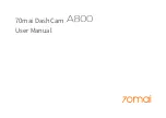
Mount the camera as required by the application.
–
Connect the Ethernet cable from "B" on the camera to the
network.
–
Connect the power supply to "3" on the QX-1.
–
Connect the photo sensor to "T" on the QX-1.
–
Connect the "Common" cable to "2" on the QX-1 and "A" on the
camera.
–
Plug in the power supply.
2.
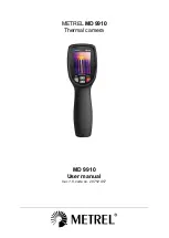
Select your Vision HAWK in the AutoVISION Connect view, create a
job, and adjust camera settings.
AutoVISION's
Connect
view allows you to select your device and
configure its settings, and to create a new job. The
Select Device
dropdown menu provides a list of available devices. Hover the mouse
over a device to see its details.
Summary of Contents for Vision Hawk Smart Camera
Page 1: ...Vision HAWK Smart Camera Guide 84 016800 02 Rev J...
Page 12: ...Chapter 1 Introduction 1 6 Vision HAWK Smart Camera Guide...
Page 24: ...Chapter 2 System Components 2 12 Vision HAWK Smart Camera Guide PNP Output for Host Input...
Page 28: ...Chapter 2 System Components 2 16 Vision HAWK Smart Camera Guide Input Output Wiring...
Page 62: ...Appendix A Connector Pinouts A 4 Vision HAWK Smart Camera Guide...
Page 68: ...Appendix B Cable Specifications B 6 Vision HAWK Smart Camera Guide...
Page 78: ...Appendix C General Specifications C 10 Vision HAWK Smart Camera Guide...
Page 86: ...Appendix D CloudLink Web HMI D 8 Vision HAWK Smart Camera Guide...
Page 98: ...Appendix F Vision HAWK Boot Modes F 4 Vision HAWK Smart Camera Guide...