Chapter
2
System Components
2-18
Vision HAWK Smart Camera Guide
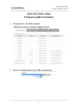
Expected Power and Ground Connections for Proper Operation
Grounding Notes:
•
Ensure that mounting bracket “Earth” is at the same potential as
power source “Earth”.
•
Supply “Return” and “Earth” ground must be stable, low-impedance
reference points.
•
“2-Terminal Power Supply” must still provide an “Earth” connection to
the imager.
•
“Signal Ground” can be used for communications and/or discrete signal
ground reference. It must
not
be used as Power Ground or Earth
Ground.
Summary of Contents for Vision Hawk Smart Camera
Page 1: ...Vision HAWK Smart Camera Guide 84 016800 02 Rev J...
Page 12: ...Chapter 1 Introduction 1 6 Vision HAWK Smart Camera Guide...
Page 24: ...Chapter 2 System Components 2 12 Vision HAWK Smart Camera Guide PNP Output for Host Input...
Page 28: ...Chapter 2 System Components 2 16 Vision HAWK Smart Camera Guide Input Output Wiring...
Page 62: ...Appendix A Connector Pinouts A 4 Vision HAWK Smart Camera Guide...
Page 68: ...Appendix B Cable Specifications B 6 Vision HAWK Smart Camera Guide...
Page 78: ...Appendix C General Specifications C 10 Vision HAWK Smart Camera Guide...
Page 86: ...Appendix D CloudLink Web HMI D 8 Vision HAWK Smart Camera Guide...
Page 98: ...Appendix F Vision HAWK Boot Modes F 4 Vision HAWK Smart Camera Guide...