background image

MICOM-3F/3T/3R HF-SSB Owner’s Guide


136


Bottom Flap

 (Open)

Battery
Cover

Battery

Holder

Battery

Clamps

(2 places)

Battery

Protection Flap

(Open)

Harness

Frame

Retaining
Straps

Battery
Frame

Power Cable

to Transceiver


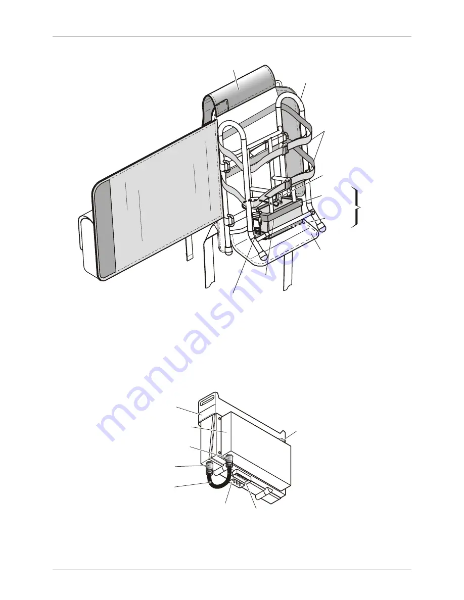
Figure 25. Typical Backpack Carrying Harness, Open View 

micomTrooper 3 Transceiver 

Figure 26 shows a general view of the micomTrooper 3 transceiver, and its connectors. Note the 
coaxial cable connecting the transceiver to the automatic antenna tuner (ATU). 

micomTrooper
Transceiver

Automatic Antenna
Tuner (ATU)

ATU RF Connector

Transceiver
RF Connector

Power

 Connector  Accessories

Connector 

Coaxial Cable

Whip Mount


Figure 26. micomTrooper 3 Transceiver, General View 

Summary of Contents for 3f

Page 1: ...Owner s Guide Part I Operation Installation 6886867J01A MICOM 3F 3T 3R HF SSB Transceivers ...

Page 2: ......

Page 3: ...MICOM 3F 3T 3R HF SSB Transceivers MOBAT USA 1720 West Paul Dirac Drive Tallahassee 32310 FL United States of America Owner s Guide Part I Operation Installation Cat No 6886867J01A ...

Page 4: ......

Page 5: ...ng 17 Using the Channel Mode 18 Using the Frequency Mode 22 Using the Scan Mode 30 Using the BIT Mode 31 Locking the Radio 32 Changing the Password 33 Using Automatic Link Establishment ALE 34 ALE Capabilities and Features 34 Using ALE Functions in the Channel Mode 43 Entering the ALE Mode 43 Receiving and Transmitting Calls in ALE Mode 45 Using the Programming Mode 78 Programming the Radio Parame...

Page 6: ...tion 104 GPS Receiver Functions 104 GPS Antenna 105 Operating the GPS Receiver 106 Installation 110 General 110 Base Station Installation 111 MICOM 3R Installation 112 MICOM 3F Installation 113 MICOM 3T Installation 113 Installation Procedures 115 Connectors 120 Maintenance 124 Introduction 124 Preventative Maintenance 124 Using BIT 125 Troubleshooting 127 Service 129 Appendix A micomTrooper 3 5 5...

Page 7: ...D Ground GPS Global Positioning System HF High Frequency HSM High Speed Modem LED Light Emitting Diode LQA Link Quality Analysis LSB Lower Side Band LSM Low Speed Modem MCW Modulated Continuous Wave MRC MICOM Radio Control Application OCXO Oven Controlled Crystal Oscillator PEP Peak Envelope Power PLL Phase Lock Loop PTT Push To Talk RGC Receiver Gain Control RSS Radio Service Software RTTY Radio ...

Page 8: ... in 1 sec steps ALE Per FED STD 1045B and MIL STD 188 141B JITC certified Frequency Stability 0 6 ppm 0 1 ppm optional 30 to 60 C Frequency Drift Aging 1 ppm year Synthesizer Lock Time 10 msec max Frequency Resolution 10 Hz Operating Temperature Range 30 to 60 C Storage Temperature Range 40 to 85 C Humidity Max 95 50 C Remote Control Interface RS 232C optional Modes of Operation 3E SSB R3E PILOT H...

Page 9: ...5 0 1 ppm High Stability Option ABZ9QCC1634 Vibration US MIL STD 810C Method 514 2 US MIL STD 810D 514 3 US MIL STD 810E 514 4 Shock US MIL STD 810C Method 516 2 US MIL STD 810D 516 3 US MIL STD 810E 516 4 Military and Industrial Standards Rain US MIL STD 810C Method 506 1 US MIL STD 810D 506 2 US MIL STD 810E 506 3 Dust US MIL STD 810C Method 510 1 US MIL STD 810D 510 2 US MIL STD 810E 510 3 Salt...

Page 10: ...ion 50 dB P E P Undesired Sideband Suppression 55 dB P E P Audio Distortion 2 5 1 2 Power Microphone Sensitivity 25 to 125mV RMS 600 Ω Hum Ripple 50 dB Inband Noise 60 dB 30 Hz BW TX RX Switching Time 10 msec Transmitter Tx Tuning Adjustments None Receiver Sensitivity SINAD SSB 0 5 µV for 10 dB SINAD 0 35 µV typical see Note 1 on page vii 0 1 to 1 6 MHz with reduced performance 1 2 Rated Power Sen...

Page 11: ...page vii Receiver Tuning Adjustments None Preselector Sections Sub octave 1 6 MHz to 30 MHz range Maximum Antenna Input 20 kV transient 100V RMS for 2 minutes Controls Standard and optional Volume on off scroll squelch scan USB LSB call monitor priority function and accessory programming connector Note 1 Values noted as Typical are valid over 90 or more of the frequency range Note 2 Optional for a...

Page 12: ...d General Safety Precautions The following are general safety precautions that are not related to any specific procedures and therefore do not appear elsewhere in this publication These are recommended precautions that personnel must understand and apply in addition to the precautions listed in the Information for Safe Efficient Operation section page ix Warning High Voltage Do not touch the anten...

Page 13: ... LIMITS IN APPLICABLE NATIONAL AND INTERNATIONAL STANDARDS The information provided in this document supersedes the general safety information contained in user guides published prior to February 2002 Compliance with RF Energy Exposure Standards NOTICE This radio is intended for use in occupational controlled applications where users have been made aware of the potentional for exposure and can exe...

Page 14: ...c energy This radio complies with the IEEE FCC and ICNIRP exposure limits for occupational controlled RF exposure environments at usage factors of up to 50 talk 50 listen In terms of measuring RF energy for compliance with FCC exposure guidelines your radio radiates measurable RF energy only while it is transmitting during talking not when it is receiving listening or in standby mode Your two way ...

Page 15: ... release the PTT button Transmit only when people outside the vehicle are at least 7 feet from a properly installed externally mounted antenna Install mobile antennas at the center of the roof or the center of the trunk deck per specific guidelines and instructions in the Radio Installation Manual These mobile antenna installation guidelines are limited to metal body vehicles Use only the approved...

Page 16: ...electromagnetic compatibility It may be necessary to conduct compatibility testing to determine if any electronic equipment used in or around vehicles or near fixed site antenna is sensitive to external RF energy or if any procedures need to be followed to eliminate or mitigate the potential for interaction between the radio transmitter and the equipment or device Facilities To avoid electromagnet...

Page 17: ...Sparks in a potentially explosive atmosphere can cause an explosion or fire resulting in bodily injury or even death The areas with potentially explosive atmospheres include fueling areas such as below decks on boats fuel or chemical transfer or storage facilities and areas where the air contains chemicals or particles such as grain dust or metal powders Areas with potentially explosive atmosphere...

Page 18: ...MICOM 3F 3T 3R HF SSB Owner s Guide Intentionally Left Blank xiv ...

Page 19: ...oper 3 the 5 to 50W backpack transceiver version of MICOM 3 transceiver and its Battery Charger FLN9541 For convenience the manual is divided into two Parts Part I Operation and Installation this Part presents the information you need to familiarize with MICOM 3 radios and operate them efficiently It also explains how to install your radio set and correct most of the problems that may occur during...

Page 20: ...rnal temperature exceeds the maximum permitted temperature the output power is automatically reduced to avoid any fault due to excessive heat Antenna mismatch protection is also included If the VSWR Voltage Standing Wave Ratio rises to more than 2 1 the transmission will be inhibited to avoid damage and a message will be displayed Receiver Features The radio utilizes digital signal processing for ...

Page 21: ... RSS The following radio features can be programmed Up to 200 simplex half duplex channels supporting SSB J3E AME H3E or Pilot R3E modes Up to four levels of output power up to 125W PEP and average Five scanning groups of up to 200 channels each with guard channel For further details refer to MICOM Radio Control Application Owner s Guide Publication 6886869J01 or to MICOM 3 HF SSB Transceiver RSS ...

Page 22: ...anumeric data Function Keys Activate different functions as displayed next to each key Microphone Connector Connector for microphone with PTT and cable to RSS Connector for Optional External USB Keyboard Move cursor to the left MORE Key Displays additional menu options when appear in the display Û Also serves to move the cursor to the right Displays the main menu Display Internal Speaker Tx Indica...

Page 23: ...to enter alphanumeric data Function Keys Activate different functions as displayed next to each key Microphone Connector Connector for microphone with PTT and cable to RSS Move cursor to the left Displays the main menu Display Tx Indicator Lights when radio is transmitting Up Down Keys Used to scroll values ON OFF Volume Control Turns radio on and off and controls the speaker volume Not used MENU ...

Page 24: ...as displayed next to each key Microphone Connector Connector for microphone with PTT and cable to RSS Audio Connectors Connectors for external speaker and handset Connector for Optional External USB Keyboard Move cursor to the left Internal Speaker Internal Speaker ON OFF Switch Display Tx Indicator Lights when radio is transmitting Up Down Keys Used to scroll values ON OFF Volume Control Turns ra...

Page 25: ...cessories connector 44 pin male D type connector used to connect the radio to external accessories such as personal computers MRC external modems Morse key etc 3 DC connector 3 pin D type male connector for connection of DC power source 4 Grounding screw Connection of ground to the radio case 5 GPS antenna connector Connection to the GPS antenna for MICOM 3 with the optional GPS receiver ...

Page 26: ...he current working mode Other Indications The following indications may appear in the work area of the LCD display to indicate functions that are active when you work with MICOM 3 Indication Meaning USB Using upper sideband for transmission and reception LSB Using lower sideband for transmission and reception SQ Squelch is active the speaker is turned on only when the radio identifies speech to pr...

Page 27: ...base line its length indicates the fraction of power reflected because of antenna VSWR the length should be small relative to the total height of the indicator which is proportional to the forward power Audible Indications The user can configure the MICOM 3 to generate audible tones to indicate events related to the radio operating conditions The tone volume low or high may also be set using the R...

Page 28: ... confirm the selection by pressing the ENTER key To let you go back to previous options there is an ESC key Using the Keypad Each key is imprinted with a numeral and several letters These characters are accessed in clockwise order as follows A single key press enters the numeral Two consecutive key presses enter the first letter Three consecutive key presses enter the second letter Four consecutiv...

Page 29: ...usly scrolls the channels in the selected direction In the Frequency mode you can change the frequency in the corresponding direction In the radio Programming mode you can use these keys to scroll among the programmable parameters Up More Down Selection from List of Predetermined Values When the parameter you want to select can assume only one of several predetermined values you select the desired...

Page 30: ...ed digits and restores the original value View Mode When the string to be displayed is longer than the number of characters that fit in one line for instance with long addresses or messages the view mode enables scrolling to the rest of the string The view mode is indicated by the symbol next to one of the function keys MICOM 3 EDIT ERAS AMD 0 01 AMD MESS When you press the key functions change HO...

Page 31: ...e keyboard functions Keyboard Key MICOM Panel Key Function ESC Esc P Cancels the last action and reverts to the previous screen Pressing ESC for a few seconds initiates AllCall F1 F2 F3 F4 F1 F2 F3 F4 Action in accordance with current screen F5 to F12 No function ENTER key Confirm action save the selection and or value SHIFT and or Changing the display contrast SHIFT or Use in AllCall AnyCall or w...

Page 32: ... ESC key The deeper you are in the menu the more times you need to press ESC Selecting the Display Language 1 Display the second part of the Menu screen as explained above MICOM 3 LOCK PROG PSW DIM MENU I 2 Press PROG F2 to enter the Programming mode MICOM 3 RAD ALE LANG PROG 3 Press the function key next to the desired language 4 Confirm the selection by pressing the ENTER key MICOM 3 LANG ENGLIS...

Page 33: ...io automatically sets up a link on the best free frequency that can be found The sets of parameters needed for this operation mode are stored under net numbers 1 to 20 SCAN SCAN mode when ALE is not used you can define a set of channels to be scanned before starting a call The scan parameters are always loaded with the MRC together with the other operational parameters but cannot be changed using ...

Page 34: ...ws SELF TEST for a few seconds Note If the display is too dim adjust its brightness using MENU CHAN MORE DIM MICOM 3 SELF TEST If the self test procedure is successfully completed the radio automatically resumes operation in the last used mode CH ALE SCAN or FREQ MICOM 3 BAND SQ DSP CH 1 F 14 000 00 USB I SQ Note If automatic dimming is enabled DIM ALT is YES the display may turn off after a few s...

Page 35: ...ve calls When the radio identifies a call addressed to it it sounds a beep and if it is a voice message you start hearing it in speaker or in the handset or headset connected to the radio The display shows the name of the calling station blinking and the call type The display now shows the RX indication which is proportional to the received signal strength Strong received signal Weak received sign...

Page 36: ...irst CW PTT LSM Low speed data First data PTT Note When the filter bandwidth is set to CW the following CW bandwidths can be configured in the Programming mode 0 25 K 0 5 K or 0 8 K Using the Channel Mode The Channel mode is used for choosing channels already programmed in the MICOM 3 The following sections describe how to use the Channel mode Selecting the Channel Mode In general the MICOM 3 auto...

Page 37: ...switch to the channel transmit frequency appears only when using a duplex or Tx only channel After releasing the radio returns to the receive frequency MICOM 3 TXM BAND SQ DSP CH 1 T 15 000 00 USB I Note For a MICOM 3 with the VP 116 option this position displays PVT or CLR for the vocoder option you may also see DGTL respectively Pressing F1 then toggles the operating mode of the VP 116 or vocode...

Page 38: ...R LOW USB SQ MODE MORE F2 selects the operation mode SSB AME or PLT MICOM 3 SSB AME PLT CH 1 MODE SSB USB SQ AGC MORE F3 controls the automatic gain control function fast slow off MICOM 3 CH 1 AGC FAST USB SQ PWR MODE AGC BW I BW MORE F4 selects the filter bandwidth MICOM 3 CH 1 BW 2 7 USB SQ 2 1 2 7 3 0 3 3 I RCLV MORE MORE F1 displays the receive level when F1 is pressed When ALE is active three...

Page 39: ...LE Enabled Note 1 MON ON OFF SEND CHAN SEND PAGE CHAN SEL SEND PAGE CHAN SEL SEND PAGE CHAN SEL SEND PAGE CHAN SEND PAGE GLOB SEL More MULT GPS Note 2 Figure 2 Channel CH Menu Notes The RCLV item appears only if the received signal level display is not permanently enabled using MENU PROG RAD PRMT RCLV The GPS item appears only if your radio includes the GPS option Choosing a New Channel To choose ...

Page 40: ... Step 1 Enter Channel mode if not in already Step 2 Press the digits 1 and 2 on the keypad The number 12 blinks in the LCD display Step 3 Press ENTER to confirm your choice 1 G P H R I S 4 7 Q J M K N L O 5 6 T U V 8 9 A D B E C F 2 3 0 Y W Z X MENU Esc P GPS ALARM 12 Using the Frequency Mode Frequency mode is used to receive and transmit on a specific frequency You can select the frequency type c...

Page 41: ...ed for Transmission T Reception R or both transmission and reception F 3 To use the displayed frequency and frequency type press ENTER If the Frequency type is Duplex press ENTER twice to accept both transmission and reception frequencies or Change the frequency type and the frequency as explained below To change the current frequency frequencies 1 If you are not in Frequency mode press MENU to ac...

Page 42: ...quency value that you want to change The blinking digit indicates the cursor location Press UP DOWN to scroll to the value of your choice Method B Type the frequency on the keypad The frequency digits blink indicating that the selection has not yet been confirmed When the desired frequency is displayed press ENTER to confirm your choice MICOM 3 BACK CLR SMPX F 12 345 67 USB SQ 4 If you are using t...

Page 43: ...hat enables you to operate the transceiver simultaneously on two different channels designated A and B Using the A B function you can freeze the frequency of channel A switch to channel B and then return to channel A again Using the A B option you can copy the frequency of the current channel to another channel To operate the VFO function 1 If you are not in the Frequency mode enter the Frequency ...

Page 44: ...you wish to change and then type the desired digit on the keypad When F3 and F4 are used in conjunction with the UP DOWN scroll keys the frequency digit scrolls according to the location of the cursor For instance if the current frequency is 7 500 54 and the cursor is at the 100 kHz location 7 _00 54 pressing the UP DOWN scroll keys will scroll the 100 kHz digit to 7 400 54 7 600 54 7 700 54 and s...

Page 45: ...USB SSB AME PLT ON OFF ON OFF 200 OFF 200 CLIP NB ATTN NF Note 1 T R A B A B A B LOW MED HIGH MAX SMPX DPLX RXO TXO VP PVT CLR VP 116 only VCD PVT DGTL CLR Vocoder only T R Select options GPS More Frequency Change Note 2 Figure 3 Frequency FREQ Menu Notes 1 The RCLV item appears only if the received signal level display is not permanently enabled using MENU PROG RAD PRMT RCLV The GPS item appears ...

Page 46: ...B SQ NF F2 controls the notch filter off lower frequency higher frequency MICOM 3 FREQ NF OFF USB SQ Note The CLAR F1 and NF F2 function keys are not available for TXO transmit only channels CLIP F3 toggles the clipper on off MICOM 3 FREQ CLIP OFF USB CLAR NF CLIP NB I SQ NB F4 toggles the noise blanker on off MICOM 3 FREQ NB OFF USB CLAR NF CLIP NB I SQ ATTN MORE F2 toggles the attenuator on off ...

Page 47: ...cy with greater ease Storing Frequencies You can store specific frequencies and frequency parameters in channels which you have programmed see Programming Channels on page 82 To store a frequency in a channel 1 If you are not in the Frequency mode press MENU to display the Menu screen MICOM 3 CHAN FREQ ALE BIT MENU I 2 Press FREQ F2 The last used frequency blinks and the frequency type is displaye...

Page 48: ...CAN BIT MENU I 2 Press SCAN F3 The last used group flashes in the display Note You can use the Scan function only after at least one group has been downloaded by means of the RSS or MRC If no scan group is stored in the radio after selecting Scan you will see NO GROUPS and then the display skips to the PROG menu 3 If you want to use the currently displayed scan group press ENTER or Press the funct...

Page 49: ...essing results in a 1 second change GRP F4 selects a scan group The other options are identical to those available in the Channel mode see the Channel Mode Options on page 19 Note The changing of the channel options is temporary When you exit the Scan mode and then return to Scan all the current options will be lost and replaced by the values configured for the various channels Using the BIT Mode ...

Page 50: ...anging the Password on page 33 for details on selecting a new password To lock the radio 1 Press MENU to display the Menu screen MICOM 3 CHAN FREQ ALE BIT MENU I 2 Press MORE to scroll to the second Menu screen MICOM 3 LOCK PROG PSW DIM MENU I 3 Press LOCK F1 MICOM 3 LOCK PSW _ 4 Enter the password to lock the radio Note If you enter the wrong password you will see WRONG PSW Enter the password aga...

Page 51: ...CK PROG PSW DIM MENU I 3 Press PSW F3 MICOM 3 PSW OLD _ 4 Enter the old password using the keypad When you start to enter the password you can use the function keys to move the cursor to the left or right or to clear the display and enter the complete string MICOM 3 O K CLR PSW OLD Note If you have not yet set a password use the factory defined password 123456 5 Press O K F1 after you enter the ol...

Page 52: ...ith other ALE users and features such as messages stack and quick call The following sections present an overview of MICOM 3 ALE capabilities and services and then provide instructions on using ALE ALE Capabilities and Features Scanning The method used to select the best channel is based on scanning as long as it is idle a radio operating in the ALE mode switches frequency at a relatively rapid ra...

Page 53: ...r sounding cycle can be programmed to 30 60 90 or 120 minutes when the automatic sounding is on You can also manually initiate sounding when there is a specific need for it even if the system is set to operate in the automatic mode A short sounding cycle ensures a more updated LQA memory However frequent sounding increases network occupancy leaving less channel free time for the users Figure 4 ill...

Page 54: ... sounding can be used LQA Memory The ALE builds a database of connectivity information based on calls and the ALE sounding messages transmitted by other stations in the network This information is stored in a special LQA memory and is used to determine the link quality of all channels in the networks The data in the LQA memory is time weighted that is recent information is given more value than ol...

Page 55: ...9 Two utility characters The stuffing symbol It can be used to add characters at the end of an address so that the resulting length is a whole number of words triplets A receiving station then interprets only the non stuffing characters For example if the address has 8 characters add one at the end of the address whereas for an address with 7 characters two symbols must be added In special address...

Page 56: ...ion is inhibited AnyCall global address see also Table 2 all the stations stop scanning and respond in randomly selected timeslots unless this function is inhibited A B option Selective AnyCall address each station with same last character s A or B stops scanning and responds in a randomly selected timeslot unless this function is inhibited using its own address A B C D option Double selective Any...

Page 57: ...xamples of patterns using the wildcard symbol Table 2 Use of Wildcard Symbol Pattern Interpretation A B C Standard 3 character address shown here for reference All the characters in this word must be evaluated A B A C B C Standard wild 1 address word Indicates that only the positions occupied by other characters A and B need be evaluated the position occupied by the symbol can be ignored ignored i...

Page 58: ...the addresses of the desired subgroup of receiving stations that is it replaces the with an alphanumeric see more details in Table 1 Any station whose address matches the pattern stops scanning and listens The operator can always initiate an outgoing transmit AllCall but the MICOM 3 can be programmed to accept or ignore incoming receive AllCalls When a radio issues an AllCall all the stations that...

Page 59: ...formation sent with the inlink address For example any station can use the inlink address to send an AMD message that all the linked stations would present to their user The inlink address is recognized only after a link is established between two or more stations Using the MultiNet Feature Normally a radio operating in the ALE mode receives and transmits only in its currently selected net However...

Page 60: ... be up to 90 characters long Messages can be added to any type of call whether individual group net AllCall AnyCall bidirectional handshake etc You can create up to 12 messages and can edit or erase any of the messages at any time Using the Caller Stack The caller stack is an internal memory that stores a list of unanswered calls Each stack entry contains the self address of the calling station an...

Page 61: ...ity as explained on page 87 MICOM 3 CHAN FREQ ALE BIT MENU I 2 Press ALE F3 The last active net flashes in the display MICOM 3 ALE NET 7 3 To use the displayed net press ENTER To select another net Press the UP DOWN keys until you reach the required number or Use the keypad to enter the desired net number The new net number blinks indicating that the selection has not yet been confirmed MICOM 3 AL...

Page 62: ...atures you can use the front panel of the radio as described in the ALE Programming section The ALE features can also be preprogrammed using the MRC or RSS ALE Mode Options Figure 5 shows the operator options available in the ALE mode MICOM 3 CALL LQA MON ALE NET 1 1 USB MON CALL SEND PAGE CHAN More ALL NET GRP ANY WILD SELF LQA ON OFF SEND PAGE CHAN MULT More NET SEND PAGE CHAN MON ON OFF SEND ED...

Page 63: ...us channels programmed for use by your radio All types of calls except for sounding calls can also carry messages Note MICOM 3 also supports the MultiNet feature When this feature is enabled it can receive and transmit ALE calls in several different nets up to 20 See details on page 41 During ALE calls a link is established between the stations participating in the call During the link state the r...

Page 64: ...r the call At the end of the AllCall the radio automatically returns to the scanning mode When an AllCall is received the display flashes an AllCall alert that alternates ALLCALL with the calling station name MICOM 3 ALE ALLCALL MICOM 3 FROM ABC Receiving an AnyCall Note You can program your radio to ignore incoming AnyCalls If the radio is set to ignore incoming AnyCalls it stops scanning when an...

Page 65: ... and the received message are stored in the stack and the STAK F3 function key appears To answer an incoming call Press any key including PTT but not ESC to accept the call The calling station name stops blinking and is displayed steadily The alert tone is no longer heard The radio is now in the link state with the calling station MICOM 3 LQA MON FROM ABC Note When an AllCall is received no link i...

Page 66: ... the following functions using the function keys Note The change of link options is temporary When you exit the link state all the changed parameters will be lost To select link mode options F1 activates the View mode where you can view the entire station address when over 11 characters as well as received messages if any when over 11 characters MICOM 3 LQA MON FROM ABC PACK A PAGE F2 enables you ...

Page 67: ...PL function is available only for individual calls and only for the call initiator The RPL F1 key is displayed only if you established the link in the ALE mode in the Channel mode this function is not available because the call is received transmitted on the current channel BAND MORE F2 toggles between upper sideband USB and lower sideband LSB The sideband change takes places only after the curren...

Page 68: ... MED HIGH MAX LINK POWER LOW USB SQ MODE MORE MORE F2 selects the operation mode SSB AME or PLT MICOM 3 SSB AME PLT LINK MODE SSB USB SQ AGC MORE MORE F3 controls the automatic gain control function fast slow off MICOM 3 PWR MODE AGC BW LINK AGC FAST USB I SQ BW MORE MORE F4 selects the filter bandwidth MICOM 3 2 1 2 7 3 0 3 3 LINK BW 2 7 USB I SQ RCLV MORE MORE MORE F1 displays the receive level ...

Page 69: ...tack stores information about unanswered calls The stack entry contains the self address of the calling station and any message sent by the calling station when it sent the call set up request The stack can contain up to 10 calls The radio records an address in the stack only once even if the same caller made several unanswered calls However if the same caller sent calls with different messages al...

Page 70: ... together with all other calls from the same address To remove an address from the stack The radio automatically removes an address from the stack in the following cases When the operator calls a station registered in the caller stack all stack calls containing that address are erased from the stack regardless of whether the call was returned from within the stack or during an individual call The ...

Page 71: ...tations members of the specified net When the MultiNet function page 41 is disabled the destination net is always the currently selected net its number is displayed on the LCD while the radio is scanning Therefore if you do not want to select a different net you can skip directly to the selection of the destination station s MICOM 3 CALL LQA MON ALE NET 1 1 USB MON When the MultiNet function is en...

Page 72: ...o select a different station Press the UP DOWN keys to scroll between stations MICOM 3 CALL 1009 or Use the keypad to enter a station name and then press SAVE F1 or ENTER when the required station name appears MICOM 3 SAVE CLR CALL 1234 Note When scrolling between stations with the UP DOWN keys every key pressing displays destination addresses in the following order The last called address The AII...

Page 73: ... If you want to call again the same station double press the PTT to use the quick call feature see page 57 To transmit an individual call with MultiNet ON 1 Press CALL F1 The radio displays the current net number flashing If you wish to change the currently used net press the UP DOWN keys or enter the net number on the keypad MICOM 3 ALE NET 7 2 Press ENTER to confirm the net number 3 The radio di...

Page 74: ... the called station has been edited and the new station name is not in the directory the channel displayed after pressing BEST F3 is the first scanned channel of the net or Press the UP DOWN keys to scroll to the channel of your choice Note You can use this option to transmit a call to a station operating in the Channel mode If the other station is in the Channel mode your radio switches to the Ch...

Page 75: ...age The first time the station is switched to the ALE or Channel mode quick call is not possible as no most recent station data exists To send a quick call Double press the PTT of your microphone or handset The radio automatically tries to contact the last called station During this process you will see TO alternating with the number of the channel on which the set up request is being sent the cha...

Page 76: ...PAGE F2 if you want to attach a message to the call or to replace edit a preprogrammed attached message See page 59 MICOM 3 SEND PAGE MON CALL 1009 I Note If the Autodial number you enter is not programmed the message NOT PROG will be displayed 3 Press CHAN F3 if you want the call to be initiated on a specific channel See page 59 4 Press ENTER or SEND F1 to start the call 5 The radio now starts th...

Page 77: ...call with a message 1 Initiate a call as explained above page 54 or 55 and select the desired station MICOM 3 SEND PAGE CHAN CALL 1009 I 2 Press PAGE F2 to add a message The last sent message is displayed MICOM 3 SEND EDIT CHAN AMD 5AM 3 You may now select a different stored message or edit this message Press the UP DOWN keys to scroll to the required message MICOM 3 SEND EDIT CHAN AMD11 11 AMD ME...

Page 78: ... CHAN AMD11 11 AMD MESS 4 The radio now starts the link set up process for this message this process is similar to the process used to set up the link for this call During this process you will see TO alternating with the number of the channel being used Notes While the radio is initializing the link you can press STOP F1 or ESC to abort the entire process If the link needed to send the message to...

Page 79: ...sary press MORE again to display the next page Note Pressing MORE again return you to the first page of special calls do not use the ESC key as it cancels the MULT option MICOM 3 WILD SELF CALL I 5 Go to the page listed below for detailed instructions Option Capabilities See Page ALL AllCall call directed to all the other stations simultaneously usually used as a distress call 62 NET Net call call...

Page 80: ...ed net or on the best scanned channel of the net Note When radios in other nets have their MultiNet feature enabled AIICalls may also reach these radios See details on page 41 There are two ways to send a global AllCall using the ESC key or using the CALL function A selective AllCall can be sent only using the CALL function To send global AllCall using the ESC key 1 Press ESC continuously for a fe...

Page 81: ...ALL I 3 Press PAGE F2 if you want to add a message to the call See page 59 for details 4 Press SEND F1 or ENTER to start the call The call now proceeds as for call initiated by pressing the ESC key To send selective AllCall 1 Press CALL F1 The radio displays the last called address MICOM 3 SEND PAGE CHAN CALL 1001 I 2 Press MORE once MICOM 3 MULT CALL GL ALLCALL I 3 Press MULT F1 to display the fi...

Page 82: ...send a global AllCall press GLOB F3 MICOM 3 SEND PAGE GLOB SEL CALL SL ALLCALL 8 Press SEND F1 or ENTER to start the call The radio starts sending the selective AllCall Note While the radio is initializing the link you can press STOP F1 or ESC to abort the entire process MICOM 3 STOP TO SL ALLCALL MICOM 3 STOP CH 2 SL ALLCALL 9 After a delay you will see LINK and you can start talking MICOM 3 PAGE...

Page 83: ...CHAN CALL 1001 I 2 Select the NET option as explained on page 61 MICOM 3 SEND PAGE CHAN CALL NET 1 3 Press PAGE F2 if you want to attach a message to the call 4 Press CHAN F3 if you want to initiate the call on a specific channel 5 Press SEND F1 or ENTER to initiate the call The radio now starts the link set up process During this process you will see TO alternating with the number of the channel ...

Page 84: ...ng word in one group is 5 If more are included then when you try to send the call you will see UFA WRONG In this case remove addresses to make the group more homogenous To make a group call first you must specify the stations to be included in the group The addresses of the stations you include in the group can be saved as a group the radio can store up to 4 different groups If a group including t...

Page 85: ...CALLING To define or change a group 1 Press CALL F1 and select the GRP option as you do to start a group call page 66 2 The first group displayed is always group 1 If this is the group you want skip directly to Step 3 below otherwise press the UP or DOWN arrows until you see the desired group MICOM 3 SEND PAGE CHAN SEL CALL GRP 1 3 To select the stations you want in this group press SEL F4 Note Th...

Page 86: ...an set your radio so that it cannot send AnyCalls AnyCall is somewhat similar to AllCall except that it requests responses from the other stations and therefore it can be used to detect new stations Another difference is that you can also select the channel on which the AnyCall will be transmitted alternatively you can let the radio select automatically the channel Note When radios in other nets h...

Page 87: ...low otherwise continue as explained below MICOM 3 SEND PAGE CHAN CALL 1001 I 2 Press MORE once MICOM 3 MULT CALL 1001 I 3 Press MULT F1 to display the first page of special calls MICOM 3 ALL NET GRP ANY CALL I 4 Press ANY F4 MICOM 3 SEND PAGE CHAN SEL CALL ANY 5 Press SEL F4 MICOM 3 ALL ENDING _ Note If you try to send SEND F1 the call without first selecting an address your attempt is rejected an...

Page 88: ... F1 or ENTER to initiate the call The radio now starts the AnyCall process During this process you will see TO alternating with the number of the channel on which the request is being sent Note You can press STOP F1 or ESC to abort the entire process When an AnyCall is transmitted the initiator of the call receives an indication of each station answering the call its address flashes in the display...

Page 89: ...ponded within this interval the maximum number of stations that are accepted in a wildcard call is 16 Therefore with the wildcard option the link set up process takes more time because the radio waits longer to get responses it cannot guess the number of stations that will answer Before continuing you may wish to review pages 37 to 41 which present details on ALE addressing including the use of wi...

Page 90: ...age to the call 10 Press CHAN F3 if you want to initiate the call on a specific channel 11 Press SEND F1 or ENTER to initiate the call Note If the selected group does not include at least 2 stations your request is rejected and you will see for a few seconds AT LEAST 2 The radio now starts the process During this process you will see TO alternating with the number of the channel on which the reque...

Page 91: ...et After going through all the channels the call process stops No other response is expected Note You can also include the self address in a group call To send a self call 1 Press CALL F1 The radio displays the last called address MICOM 3 SEND PAGE CHAN CALL 1001 I 2 Press MORE once MICOM 3 MULT CALL 1001 I 3 Press MULT F1 to display the first page of special calls MICOM 3 ALL NET GRP ANY CALL I 4...

Page 92: ...ried out either on a single channel or on all the net channels When required a message can also be added to the procedure After a bidirectional handshake with a single station the LQA matrices of both radios are updated The operator can then initiate a call to that station and obtain the best channel automatically When the bidirectional handshake procedure is performed with a net all the stations ...

Page 93: ...rocess After confirming the message exclamation mark precedes the name of the called station indicating that a message has been attached 5 Press CHAN F3 if you wish to execute a bidirectional handshake process on a specific channel 6 Press SEND F1 or ENTER in order to initiate the bidirectional handshake process During this process you will see TO alternating with the number of the channel on whic...

Page 94: ... handshake you can press STOP F1 or ESC to abort the entire process Sounding Sounding is used to test the quality of the channels and propagation paths of all channels in the net The sounding signal is normally repeated automatically at regular intervals A complete round of sounding messages or sounding cycle can be programmed to 30 60 90 or 120 minutes or can be set to OFF Sounding can also be in...

Page 95: ...o avoid disconnecting the link too soon as a result of inactivity that is after the PTT time out interval PTOT programmed under the ALE Options Configuration section each participant can request other stations to wait beyond the PTOT interval up to 10 minutes more before automatic disconnection occurs MICOM 3 RCLV FREQ TOT LINK 1001 USB This option TOT time out interval is displayed over the F4 ke...

Page 96: ...by VP 116 voice privacy unit when used by your radio set To find details on the selections available to you on the PROG menu use Figure 6 page 79 and Figure 7 page 80 Note that MICOM 3 lets you change the currently used parameters on line as required in any particular situation When you select another channel or net the changes are discarded and the programmed values are used again Note The Progra...

Page 97: ... YES NO STOR GET ERAS PWR FREQ BAND MODE BW AGC YES NO YES NO YES NO LOW HIGH YES NO 0 25 0 5 0 8 YES NO YES NO LOW MED HIGH MAX 1 2 2 4 4 8 9 6 LOW MED HIGH MAX SMPX DPLX RXO TXO LSB USB SSB AME PLT SLOW FAST OFF 2 1 2 7 3 0 3 3 LSM CW More More 1 10 LANG VP VCD Option Option ENG FRNC ESPA PVT CONF ERAS More PVT PK LLB BIT VOL 1 8 1 8 Figure 6 PROG Menu Radio Parameters Programming ...

Page 98: ... NO ALL NET DIR OPT AUTO STOR ADDR AMD YES NO More YES NO ADD ERAS AMD EDIT ERAS ALE LANG MICOM 3 MENU I LOCK PROG PSW DIM RAD MxCH AUTO 0 59 More More YES NO EXAL YES NO ALRT YES NO TOT MLQA 0 100 YES NO QCAL YES NO AADR YES NO MNT YES NO ANY YES NO WILD YES NO AMD YES NO ILNK More 1 10 PTOT ENG FRNC ESPA RCV ADD ERAS SAVE YES NO ALL YES NO ALL SAVE CLR YES NO BDLK EDIT EDIT VP VCD PVT CONF ERAS ...

Page 99: ...e following sections explain the programming procedures To enter the Radio Programming mode 1 Press MENU to display the Menu screen MICOM 3 CHAN FREQ ALE BIT MENU I 2 Press MORE to scroll to the second Menu screen MICOM 3 LOCK PROG PSW DIM MENU I 3 Press PROG F2 to enter the Programming mode MICOM 3 RAD ALE LANG PROG 4 Press RAD F1 to enter the Radio Programming mode MICOM 3 RADIO PROGRAMMING CHAN...

Page 100: ... parameters from one channel to another ERAS ERAS is used to delete erase a channel Actually this action only replaces the user modified parameters of the channel with the factory default parameters but marks the channel as not programmed PWR Select the channel transmit power level Four transmit power levels can be selected LOW 25 W nominal MED 62 5 W nominal HIGH 100 W nominal MAX 125 W nominal F...

Page 101: ...le sideband with pilot signal AGC Select the channel Automatic Gain Control mode MICOM 3 offers two AGC response speeds SLOW and FAST You can also turn the AGC OFF completely BW Select the default channel filter bandwidth 2 1 K 2 7 K 3 0 K 3 3 K LSM Low Speed Modem CW Continuous Wave The bandwidth used in this case is selected by MENU PROG RAD PRMT CW Note The factory default parameter values are ...

Page 102: ... modes is independently selected for each channel If the selected data transmit power exceeds the transmit power configured on the operating channel the radio will use the lower channel transmit power MST Enable disable the sidetone heard in the speaker when you transmit using the microphone AST Enable disable the heard in the speaker sidetone when you transmit using an accessory connected through...

Page 103: ... channel filter bandwidth used in the CW mode 0 25 250 Hz 0 5 500 Hz 0 8 800 Hz A lower value improves the reception but requires better frequency accuracy RCLV Enable disable the receive signal level display If the receive signal indication is not enabled you can temporarily enable it using one of the function keys DIM Enable disable automatic dimming of the display Usually the display operates c...

Page 104: ...he OPTS option in the Radio Programming menu provides the following options see also Figure 6 AMP Enables disables operation with an external RF power amplifier TUNE Enables disables operation with an external antenna tuner If you are using an external tuner you must set this option to YES ALE Enables disables the ALE functionality When the ALE option is disabled MICOM 3 can use the Scan Mode see ...

Page 105: ... RAD ALE LANG PROG 5 Press MORE as required to access additional ALE programming parameters MICOM 3 ALE PROGRAMMING NET DIR AMD OPT I In the ALE Programming mode you can program the following features see also Figure 7 Description See Page NET Net parameters station names options members and scanned channels 88 REC Edit the list of stations not appearing in the directory from which calls have been...

Page 106: ...ation includes the following menus NAME Edit the net name and the self address NET Define or edit the net names It is not allowed to use a name already used as a self address nor an address already appearing in the address directory SELF Define or edit your self address the identification of your station to be used by other stations within the same net It is not allowed to use a name already used ...

Page 107: ...a new network and wish to base most of its parameters on an existing network for instance if you need to use different frequencies channels for day and night communication but all other net information such as stations and names is identical ERAS Erase an entire network from the ALE data base After preparing a set of parameters your entries are checked and any errors are reported If you do not cor...

Page 108: ...his option is ON a call cannot be initiated on a channel determined to be occupied This option can be operated in addition to the ALE signal detection mechanism You can select the interval at which occupancy checks are made 300 to 3000 msec in 300 msec increments M S Master Slave select whether your radio serves as a master or slave in the current ALE network Only a master station can initiate a N...

Page 109: ...or any other key is pressed within 30 seconds from the reception of a call If Accept Link TOT is set to NO the received call is accepted immediately and automatically MLQA Minimum LQA Score determines the minimum acceptable LQA Link Quality Analysis score allowed when trying to establish a link on a specific channel If the minimum score is not achieved when the radio attempts to establish a link i...

Page 110: ...ng AMD messages ILNK Inlink enable disable the inlink facility which enables notifying other call participants when each participant disconnects from the link All participants must be programmed to use the same selection either YES or NO Do not enable the inlink function when communicating with a radio that does not support the full ALE capabilities in accordance with MIL STD 188 141B BDLK Bidirec...

Page 111: ...on details on page 59 Note If a message is attached to the address an exclamation mark precedes the address Storing ALE parameters Before exiting the ALE programming menu you must store the parameters you have programmed Important If you press the MENU or ESC key to exit programming mode without first saving your changes you will be prompted to store the ALE configuration changes Press YES to stor...

Page 112: ...dress different from all the previously detected addresses is received while 20 addresses are already stored it will replace the oldest address The information on the received addresses is automatically erased when the radio is turned off only addresses added to the directory remain in the directory To edit the received addresses and add addresses to the ALE directory 1 Press MENU F1 and select AL...

Page 113: ...tomatically starts using the specific parameters needed by the VP 116 For example you can see that when the privacy function is used the bandwidth is set to 3 3K instead of 2 7K in the clear mode operation without VP After you turn the radio off and disconnect the VP 116 the radio reverts to normal operation with a 2 7K filter bandwidth The parameter values used by the VP 116 are as follows Volume...

Page 114: ...ion SQ F3 is not displayed The Squelch option F3 appears only in the Clear CLR mode 3 When the PTT is activated a hold off tone sounds Wait for the hold off tone to end before talking To use the VP 116 unit in the Channel mode 1 Press PVT F1 whenever it is necessary to toggle between the PVT Private and CLR Clear modes MICOM 3 CLR BAND SQ DSP CH 6 F 16 000 00 USB I BW3 3K Note When using the publi...

Page 115: ...COM 3 LOCK PROG PSW DIM MENU I 3 Press PROG F2 to enter the Programming screen MICOM 3 RAD ALE LANG VP PROG 4 Press VP F4 to enter the VP 116 menu 5 Press the relevant key to access the VP 116 modes PVT F1 Select the key used in the private mode PK F2 Select the public key mode LLB F3 Activate the local loopback used to check proper operation of the VP 116 in conjunction with the MICOM 3 BIT F4 Pe...

Page 116: ... menu MENU MORE PROG VP F4 2 Press PVT F1 to enter the privacy key selection mode 3 Use the UP DOWN keys to scroll through PVT1 to PVT8 Note The key number flashes until its selection is confirmed 4 Press ENTER to confirm the selection of the key displayed on the screen Press ESC to revert to the previous setting Using the VP 116 PK Public Key Mode In the public key mode two VP 116 units can commu...

Page 117: ...a loopback from the microphone input to the speaker output this loopback remains connected until the ESC key is pressed Note No signal is actually transmitted by the radio To perform the VP 116 Local Loopback test 1 Access the VP 116 Programming menu MENU MORE PROG VP F4 2 Press LLB F3 to enter the LLB mode 3 Press the PTT and talk When everything is OK you will hear your own signal during the tes...

Page 118: ...lly switches to the protected DIG mode after the link is established and returns to scan in the Clear mode after the link is disconnected Using the Vocoder When operating the radio with the vocoder in the Channel Frequency or ALE mode you can choose between the CLR DIG and PVT private modes PVT activates the automatic voice privacy functions DIG activates the vocoder digital encryption function CL...

Page 119: ... 16 000 00 USB I BW3 3K 2 Press the F3 key whenever it is necessary to toggle between the PVT Private DIG and CLR Clear modes To use the vocoder in the ALE mode 1 Enable the ALE mode as described in Enabling the ALE Mode on page 43 2 When using the DIG mode the radio scans automatically in the CLR mode you may see that the bandwidth returns to the default 2 7K and switches to the DIG mode without ...

Page 120: ...o display the Menu screen MICOM 3 CHAN FREQ ALE BIT MENU I 2 Press MORE to scroll to the second Menu screen MICOM 3 LOCK PROG PSW DIM MENU I 3 Press PROG F2 to enter the Programming screen MICOM 3 RAD ALE LANG VCD PROG 4 Press VCD F4 to enter the Vocoder menu 5 Press the relevant key to access the Vocoder options PVT F1 Select the key used in the private mode CONF F2 Display information on the voc...

Page 121: ... keys to scroll through PVT1 to PVT8 Note The displayed key number flashes until its selection is confirmed 4 Press ENTER to confirm the selection of the key displayed on the screen Press ESC to revert to the previous setting Display of Vocoder Information 1 Access the Vocoder Programming menu MENU MORE PROG VCD F4 2 Press CONF F2 3 The screen changes to display the vocoder host version and the fu...

Page 122: ...eeds LLA format Latitude longitude and altitude LLA The latitude and longitude are displayed in degrees with a precision of hundredths of arc minutes 1 100 min the altitude is reported in meters relative to the mean sea level MSL Velocity is reported as the change in the East North and Up coordinates presented in meter sec with a precision of 0 001 meter sec ECEF format Earth Centered Earth Fixed ...

Page 123: ...ble carries both DC power for the antenna and the received GPS signals The antenna is 42 mm wide by 50 5 mm long by 13 8 mm high 1 65 1 99 0 55 and it requires a minimal ground plane of 60 by 60 mm 2 36 2 36 to provide the specified performance Selecting a Proper Location for the GPS Antenna GPS satellites transmit their special signals in the 1575 MHz range such signals do not penetrate conductiv...

Page 124: ...le at several places 3 Connect the coaxial connector of the antenna cable to the MICOM 3 GPS connector Operating the GPS Receiver GPS Menu The GPS menu is displayed by selecting the GPS item on the FREQ or CH menu The GPS menu structure is shown in Figure 11 CH Mode FREQ Mode Existing Menu MORE Existing Menu MORE MORE MORE GPS LLA Format ECEF Format FULL VERT DHOR HOR TIME DEV FRMT X Y Z DX DY DZ ...

Page 125: ...e Z axis TIME Display the time of day obtained from the GPS receiver FULL Alternating display of the absolute velocity VEL and its direction relative to the North azimuth AZIMTH DEV Used to check that the GPS receiver is operating FRMT Toggle the display format to LLA First Time Operation The internal GPS receiver is always powered when the transceiver is turned on Therefore if the GPS antenna is ...

Page 126: ...uding one to many 2 Request the position of another MICOM 3 transceiver equipped with the optional GPS receiver You can make this type of request only when you call an individual station If the request is made in the CALL mode that is before a link has been set up between the two stations a link will be set up and then the other station will automatically return an AMD message with its latitude an...

Page 127: ...LINK mode select the PAGE selection mode 2 Scroll until you see the RMT POS message and then send the message 3 The called station displays WHERE ARE YOU To send an automatic response the called operator select the PAGE selection mode and then sends the I AM AT message as explained above Alternatively the called operator may answer with a voice message What to do if 1 If the GPS display mode GPS L...

Page 128: ...r convenience of access to electrical connections and for maintenance The selected location should be clean dry and well ventilated Do not mount the unit in close proximity to strong electrical fields produced by brush motors and generators welders etc The antenna antenna tuner and associated cable kits are provided separately These should be installed before the radio is installed Follow the inst...

Page 129: ...model is available FPN5590 for 110 220 V AC 50 60 Hz 12V Battery Fuse 30A Green Output 1 max 5A Black Ground Red Output 2 max 25A Radio 5A GND 25A 5A 25A Figure 12 FPN5590 Power Supply Connections This power supply also serves as a charger for the external backup 12 V battery if connected When AC power failure occurs the battery functions as the main power source When AC power is again available t...

Page 130: ...ame Ground 12V Battery F2 7 5A Trunk Compartment Passenger Compartment Engine Compartment Outside the Car Antenna Ferrite Installation Antenna Connector Microphone Figure 13 MICOM 3R Installation Diagram Figure 14 shows the location of the installed components within the vehicle Radio ATU Antenna Cable DC Power Cable BAT Figure 14 Typical MICOM 3R Installation Within Vehicle ...

Page 131: ...m allowable high voltage lead in cable length MICOM 3F Installation The procedure shown above for the MICOM 3R is also used to install the MICOM 3F MICOM 3T Installation For MICOM 3T only the control head the speaker and the microphone are installed in the passenger compartment of the vehicle The radio transceiver is installed in the trunk of the vehicle together with the antenna tuner Figure 15 i...

Page 132: ...cated in the rear section of the vehicle the power cable extends to the battery location Notes 1 The upper installation number 1 in Figure 16 is recommended over the front installation number 2 in Figure 16 because of the covering that protects the control head from direct sunlight 2 To achieve maximum operating range the antenna should be mounted as high on the vehicle body as possible without st...

Page 133: ... to the bottom of the radio housing Step 3 Drill an additional hole for the ground bolt DC Power Connection This paragraph describes connections to a 12 V negative ground vehicular battery 12V Battery Radio Green 12 Red 8 Black 12 Fuse 30A Fuse 7 5A Connector Mobile Chassis Figure 18 DC Power Connection Step 1 Bring the power connector of the DC power cable to the radio DC power connector but do n...

Page 134: ... the lug on the black wire to the negative terminal of the battery Notes 1 It is recommended to attach the black ground wire to the vehicle s chassis The point of attachment should be located as close as possible to the radio Refer to Figure 19 2 In front installation add one ferrite supplied with the installation radio kit on the DC cable as close as possible to the radio 3 In trunk mount install...

Page 135: ...n the mounting surface 2 Secure the trunnion mounting bracket to the surface with the four 10 16 1 self drilling screws or drill a 6 mm φ hole at each location 3 Mount the control head onto the bracket and secure it with the two wing screws provided MICOM 3F 3R Final Connections Warning Ensure that the radio is off before making these connections Step 1 Connect the power cable to the DC power conn...

Page 136: ...table for grounding purposes The ground lead should be as short as possible Step 5 If desired plug an external speaker into the accessories connector Any speaker with an impedance greater than 8 ohms can be used External Speaker Installation for MICOM 3F Connect the external speaker 8Ω 8W to the accessories connector pins 1 3 The external speaker is connected in parallel to the internal speaker To...

Page 137: ...igure 21 on page 118 3 Use the tie straps included with the cable kit to tie loose cables out of the way 4 Connect a ground lead from the GND screw on the radio body to the chassis of the vehicle 5 Connect the control head cable to the connector in the front panel of the radio and to control head Important Special attention should be given to locating a good vehicle ground Optimum radio performanc...

Page 138: ... ground 7 MONITOR Mutes the speaker before transmission is enabled short momentary to ground to open speaker 8 AUDIO OUT Receive audio output to earphone 600 Ω 300 mVRMS MICOM 3R Audio Connectors The audio connectors are located on the lower left part of the radio front panel An external speaker and handset can be plugged into both connectors Table 4 lists the functions of the audio connector pins...

Page 139: ...al 8Ω 8W speaker 2 STOP SCAN Digital control input for stop scan function 3 SPKR Differential output to the external 8Ω 8W speaker 4 EXT RX AUDIO Differential received audio output 0 dBm 600Ω not controlled by volume 5 EXT RX AUDIO Differential received audio output 0 dBm 600Ω not controlled by volume 6 EXT TX AUDIO Differential transmit audio input 600Ω input impedance 0 dBm is required for full ...

Page 140: ... output to VP 116 PPS 500W ASTIC 30 AMP REV Maintain constant power at 500W transceiver output 31 RXD Receive input point to point protocol to host HLC 32 TX AUDIO OUT Input to baseband TX path 33 RXB RS 232 protocol receive input to VP 116 PPS 500W ASTIC 34 RX AUDIO OUT Input to baseband RX path 35 RX AUDIO IN Output from baseband RX path 36 AMP FWD Maintain constant power at 500W transceiver out...

Page 141: ...ng with the following installation practices and if necessary by adding some damping components it may be possible to reduce these noises to a tolerable level 1 Keep your antenna tuner and antenna as far as possible from the engine compartment 2 Connect the primary power lead of the radio directly to the battery instead of the starter relay The battery acts as a large capacitor about one farad for...

Page 142: ... this possible problem to inform the service representative accordingly Preventative Maintenance System Integrity Periodically check the integrity of your system check the power source cables including coax cables connectors antenna tuner if used and antenna Carefully check that no damage has been caused to your cables pay extra attention to runway through holes and bent cables Periodic Calibratio...

Page 143: ... memory checksum LORD board problem 09 HC16 RAM memory LORD board problem 10 No 16 8 MHz clock Check for good power cable connection Possible LORD board problem 11 Battery low Weak internal battery replace battery to correct problem 12 Control head wake up Control head problems 13 Control head is not responding Control head problems 14 Radio not programmed Problem experienced during programming Pr...

Page 144: ...est HIGH POWER board problem 31 Antenna mismatch Problem with antenna check antenna and its connections If problem persists it is a HIGH POWER board problem 32 Harmonic filter range 1 HIGH POWER board problem 33 Harmonic filter range 2 HIGH POWER board problem 34 Harmonic filter range 3 HIGH POWER board problem 35 Harmonic filter range 4 HIGH POWER board problem 36 Harmonic filter range 5 HIGH POW...

Page 145: ...e reduction Kit TLN8845 Poor or no transmission CHECK That a 30A fuse is installed in the fuse holder located on the red wire of the power cable That proper grounding cables are connected from the radio and from the antenna tuner to the vehicle chassis While speaking check RF power bars for activity The resultant RF power output is displayed in approximately 15 W increments bars being added from l...

Page 146: ... using the MRC or RSS to obtain more information If no further information is displayed the problem is in the HIGH POWER board CU LIMIT CHECK That the radio is programmed to TUNER OFF when your antenna system is not equipped with an ATU For short circuit or other damage to the antenna feed coax That the ATU is in good working condition NOT PROG displayed when the radio DC power failed during progr...

Page 147: ...1720 West Paul Dirac Drive Tallahassee 32310 FL USA support mobatUSA com Radio Checks If you suspect a radio problem check the following items before requesting service Be sure the radio is turned on Replace or recharge the battery The first time a new battery is used it should be charged for at least 16 hours The antenna must be screwed on properly with its base flush against the top of the anten...

Page 148: ...Introduction Scope This Appendix covers the installation and operation of the micomTrooper 3 the 5 to 50W backpack transceiver version of the MICOM 3 transceivers Figure 23 micomTrooper 3 Ready for Operation General View Antenna Base Whip Antenna micomTrooper Transceiver Backpack C Harness arrying Handset ...

Page 149: ...d in a convenient lightweight harness that completely envelops the transceiver The durable aluminum frame of the harness protects against damage and allows placing the transceiver on ground for static operations Equipment Description micomTrooper 3 Functional Description micomTrooper 3 is an advanced highly backpack portable HF SSB transceiver that provides a complete solution to the communication...

Page 150: ...ds Loud and clear voice communication Built in voice quality system with proprietary DSP algorithms that filter out background noises and elevates sound bytes providing exceptional communication clarity Selectable bandwidth for fine tuning and optimal voice reception Unmatched combination of high power up to 50 W and high sensitivity 0 3 µV for outstanding communication coverage Voice activated di...

Page 151: ...ed vocoder modem encryption Built in GPS receiver Various types of antennas Spare 12Ah rechargeable Lithium Ion battery AC battery charger FLN9541 Hand crank generator Portable solar panels Main micomTrooper 3 Technical Specifications Transmit Frequency Range 1 6 to 30 MHz Number of Preset Channels 200 Specifications Transmit Power 5 10 20 50 W Receive Frequency Range 100 kHz to 30 MHz Rx Sensitiv...

Page 152: ...um batteries according to the prescribed safety regulations In particular observe the following precautions 1 Do not short circuit Lithium batteries 2 Do not damage battery case and do not tamper with battery in any way 3 Do not dispose of used Lithium batteries by burning or incinerating Unpacking and Inspection a A preliminary inspection of the equipment containers should be made prior to unpack...

Page 153: ... only the antenna and the handset protrude Two storage pouches for storing accessories and or spare batteries are located to the two sides All the flaps and covers are held by Velcro fasteners Shoulder Strap Adjustment Buckle Bottom Flap Closed Storage Pouches Shoulder Straps Access Flap to Handset Connector Breast Strap Protection Flap Closed Waist Straps Harness Frame Figure 24 Typical Backpack ...

Page 154: ...pack Carrying Harness Open View micomTrooper 3 Transceiver Figure 26 shows a general view of the micomTrooper 3 transceiver and its connectors Note the coaxial cable connecting the transceiver to the automatic antenna tuner ATU micomTrooper Transceiver Automatic Antenna Tuner ATU ATU RF Connector Transceiver RF Connector Power Connector Accessories Connector Coaxial Cable Whip Mount Figure 26 mico...

Page 155: ...f by turning the volume control fully counterclockwise beyond the detent you should hear a click 1 Place the carrying harness on a level surface with the metal braces facing upward 2 If necessary open the harness protection flap Note For clarity the figure at the right does not show the harness 3 Place the micomTrooper 3 on the top of the carrying harness with its front panel upwards and its rear ...

Page 156: ... surface 2 Open the harness protection flaps to gain access to the battery holder for clarity harness is not shown 3 Release the two battery clamps holding the battery cover 4 Remove old battery if any 5 Visually check the battery battery holder and battery plug for dirt or damage Clean if necessary 6 Orient the battery as shown in figure and push the battery in place to mate connectors 7 Reattach...

Page 157: ...tor Tighten by hand only 3 Extend the flexible steel blade of the antenna 4 Screw the whip antenna into the antenna base See the figure for a general view of the transceiver after completing this step 5 To remove the whip antenna perform the above tasks in the reverse order Connection of Audio Accessories 1 Connect the handset to either of the two audio connectors on the front panel of the micomTr...

Page 158: ...aist Strap Operating Instructions Note When using the micomTrooper 3 with its whip antenna make sure to select YES for the TUNER option MENU MORE PROG RAD OPTS When using the micomTrooper 3 with a dipole or long wire antenna static operation as described on page 141 make sure to select NO for the TUNER option 1 Turn the micomTrooper 3 ON OFF switch and volume control clockwise and adjust for a com...

Page 159: ...o connect a dipole or long wire antenna 1 Turn the transceiver off 2 Open the harness envelope to reach the coaxial cable interconnecting the RF connectors of the transceiver and the ATU 3 Disconnect the cable from the transceiver RF connector 4 Connect the coaxial feed of the antenna directly to the transceiver RF connector 5 You may now remove the whip antenna see page 140 6 Close the harness en...

Page 160: ...attery contacts clean and avoid accidental short circuits by turning the charger on only after a battery is installed on the charger FLN9541 Operating Instructions 1 Place the battery charger on a flat surface protected from sun and rain 2 Insert the charger power cable plug into an AC outlet 3 Connect the battery to be charged to the battery charger place the battery socket over the charger pins ...

Page 161: ...ARGE pushbutton 7 You will be notified when the battery is fully charged the FINISH CHARGE indicator will start flashing and the tone is heard again 8 At this stage set the POWER switch to OFF and remove the battery from the charger 9 Disconnect the charger power cable from the AC outlet Main FLN9541 Technical Specifications Input voltage 90 to 265 VAC 20 to 60 Hz Charged battery voltage 16 8 0 2 ...

Page 162: ...choose a channel 21 To enter the frequency mode 23 To change the current frequency frequencies 23 To operate the VFO function 25 To return to the regular Frequency mode 26 To select frequency mode options 27 To store a frequency in a channel 29 To enter the Scan mode 30 To enter the BIT mode 31 To lock the radio 32 To unlock the radio 32 To enter the Password mode 33 To enter the ALE mode 43 Recei...

Page 163: ... function 63 To send selective AllCall 63 To transmit a net call 65 To transmit a group call 66 To define or change a group 67 To transmit an AnyCall 69 To transmit a wildcard call 71 To send a self call 73 To execute a bidirectional handshake with an individual station 74 To execute a bidirectional handshake with a net 75 To manually initiate sounding 76 To enter the Programming mode 78 To enter ...

Page 164: ...e 101 To access the vocoder programming menu 102 To select the vocoder private key to be used in this mode 103 To install the GPS antenna 106 To send your position report to other station s 109 To automatically get the position of another station 109 To send a position request to the station you are linked to 109 Fast and simple radio link establishing 132 Loud and clear voice communication 132 Us...

Reviews: