


Device control
Page 45
PROFIBUS-Manual Servo positioning controller DIS-2 48/10 FB
Version 2.0
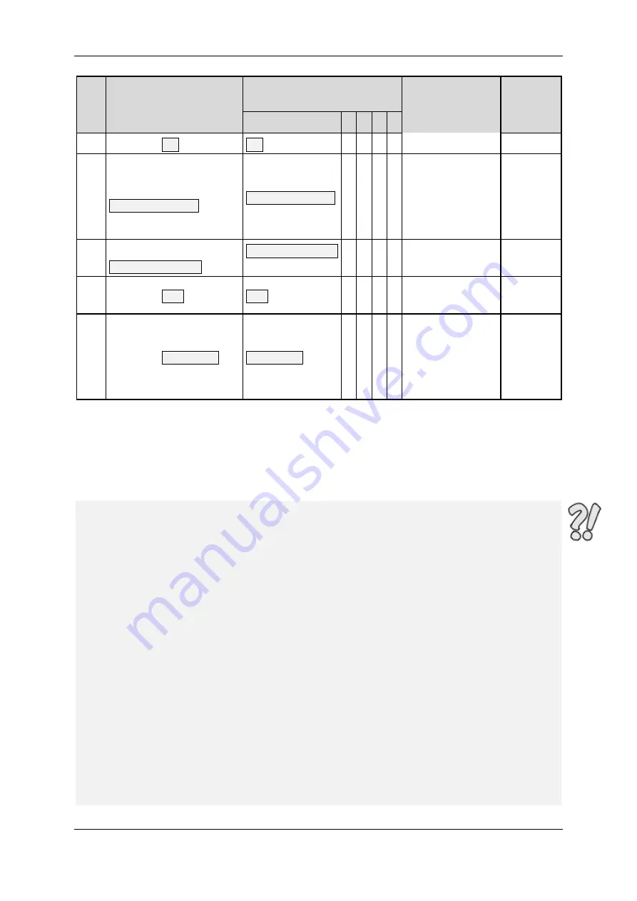
No. Will be performed if
Bit combination for control
word 1
Action
Status
word 1
1)
Bit 3 2 1 0
2
Command
ON
ON
=
0 1 1 1
0x0203
3
Command
Enable Operation
Enable Operation
=
1 1 1 1
Activation of power
stage enabling and
control in
accordance with
operating mode set
0x0207
4
Command
Disable Operation
Disable Operation
=
0 1 1 1
Cancellation of
controller enabling
0x0203
11
Command
OFF
OFF
=
x 1 1 0
Cancellation of
controller enabling
0x0201
7
Command
Coast Stop
Coast Stop
=
x x 0 x
Power stage is
disabled. The
motor coasts down
and can be rotated
freely.
0x0250
or
0x0270
1)
: After completion of the state transition. The mask for the relevant bits is 0x0277
Table 9.7:
Most important state transitions of the servo positioning controller
The following example shows the enabling of the servo positioning controller, i.e. the enabling of the
controller via the PROFIBUS field bus:
EXAMPLE
The servo positioning controller is to be “enabled”, i.e. the power stage
and the controller enabling are to be activated via PROFIBUS:
1.)
The servo positioning controller is in the
SWITCH_ON_INHIBITED
state
2.)
The servo positioning controller has to change over to the
OPERATION
state
3.)
According to the state diagram (Figure 9.1), state transitions 1, 2 and 3
have to be performed.
4.)
The following results from Table 9.7:
Transition 1: Control Word 1 = 0406
h
New state: READY_FOR_SWITCHING_ON *
1)
Status Word 1 = 0x0201
Transition 2: Control Word 1 = 0407
h
New state: SWITCHED_ON *
1)
Status word 1 = 0x0203
Transition 3: Control Word 1 = 040F
h
New state: OPERATION *
1)
Status Word 1 = 0x0207
Note:
1.)
The example assumes that no other bits are set in
control word 1.
Bit 10
must be set. Otherwise, only bits 0..3 are relevant for the
transitions.
*
1)
The master has to wait until the state can be read back in
status word 1
in the
relevant bits (mask = 0x0277). This will be explained in detail later in this
manual.


