background image

А

рхангельск

   (8182)63-90-72   

А

стана 

  (7172)727-132   

А

страхань 

  (8512)99-46-04   

Б

арнаул 

  (3852)73-04-60   

Б

елгород 

  (4722)40-23-64   

Б

рянск 

  (4832)59-03-52   

В

ладивосток 

  (423)249-28-31   

В

олгоград 

  (844)278-03-48   

В

ологда 

  (8172)26-41-59   

В

оронеж 

  (473)204-51-73   

Е

катеринбург 

  (343)384-55-89 


И

ваново 

  (4932)77-34-06   

И

жевск 

  (3412)26-03-58   

К

азань 

  (843)206-01-48   

К

алининград 

  (4012)72-03-81  

К

алуга 

  (4842)92-23-67   

К

емерово 

  (3842)65-04-62   

К

иров 

  (8332)68-02-04   

К

раснодар 

  (861)203-40-90   

К

расноярск 

  (391)204-63-61   

К

урск 

  (4712)77-13-04   

Л

ипецк 

  (4742)52-20-81

М

агнитогорск 

  (3519)55-03-13   

М

осква 

  (495)268-04-70   

М

урманск 

  (8152)59-64-93   

Н

абережные Челны 

 (8552)20-53-41  

Н

ижний Новгород 

 (831)429-08-12   

Н

овокузнецк 

 (3843)20-46-81   

Н

овосибирск 

  (383)227-86-73   

О

мск 

  (3812)21-46-40   

О

рел 

  (4862)44-53-42   

О

ренбург 

  (3532)37-68-04   

П

енза 

  (8412)22-31-16 

П

ермь 

  (342)205-81-47   

Р

остов

-

на

-

Дону 

  (863)308-18-15   

Р

язань 

  (4912)46-61-64   

С

амара 

 (846)206-03-16   

С

анкт

-

Петербург 

  (812)309-46-40  

С

аратов 

  (845)249-38-78   

С

евастополь 

  (8692)22-31-93   

С

имферополь 

  (3652)67-13-56   

С

моленск 

  (4812)29-41-54   

С

очи 

  (862)225-72-31   

С

таврополь 

  (8652)20-65-13   

С

ургут 

  (3462)77-98-35   

Т

верь 

  (4822)63-31-35   

Т

омск 

  (3822)98-41-53   

Т

ула 

  (4872)74-02-29   

Т

юмень 

  (3452)66-21-18   

У

льяновск 

  (8422)24-23-59   

У

фа 

  (347)229-48-12   

Х

абаровск 

  (4212)92-98-04  

Ч

елябинск 

  (351)202-03-61  

Ч

ереповец 

  (8202)49-02-64  

Я

рославль 

  (4852)69-52-93  

сайт:


http://www.meccalte.nt-rt.ru/ 

|

| эл. почта:

 [email protected] 

Guida Tecnica:

Regolatore Digitale DER1

Technical Guide:

DER1 Digital Regulator

Summary of Contents for DER1

Page 1: ...64 93 8552 20 53 41 831 429 08 12 3843 20 46 81 383 227 86 73 3812 21 46 40 4862 44 53 42 3532 37 68 04 8412 22 31 16 342 205 81 47 863 308 18 15 4912 46 61 64 846 206 03 16 812 309 46 40 845 249 38 7...

Page 2: ...Status Word Location L 39 pag 18 SETTING OF VOLT STAB AMP and Hz PARAMETERS pag 19 1 Voltage pag 19 1 1 Setting voltage pag 19 1 2 Soft Start pag 19 1 3 Slow voltage variations pag 20 2 Stability pag...

Page 3: ...gured to obtain the best performance most of the settings are stored in a non volatile integrated memory EEPROM The first time the regulator is turned on a default configuration will be present which...

Page 4: ...ized conditions load temperature Transient voltage drop and overvoltage within 15 Voltage recovery time within 3 of the value set in less than 300 msec Programmable Soft start Parameters VOLT STAB AMP...

Page 5: ...Range 2 TABLE 2 CONNECTOR CN3 23 Common Active protections output Current 100mA Voltage 30V Max length 30m 3 Both activating alarm and delay time are programmable 24 A P O 25 Common Jumper 50 60Hz Typ...

Page 6: ...ation overcurrent protection TABELLA 3 TRIMMERS Fig 1 INSTALLATION Upon receipt of the digital regulator perform a visual inspection to ensure that no damage has been sustained during transportation a...

Page 7: ...or connections depend on the application and excitation system Figure 1 shows the functional aspect of the connection points to the regulator An error in connection may have deadly consequences for th...

Page 8: ...tes Series star H SCC0160 H SCC0158 F N A F N A 530 550 575 600 690 760 800 920 960 from 520 to 1000 F SCC0161 F SCC0159 1200 from 1100 to 2000 F SCC0202 2 channels in series Parallel star 190 200 208...

Page 9: ...rom the Configuration Menu 4 The parameter present in parameter P 5 if three phase sensing or p 6 if single phase sensing has to be calibrated Calibration should be adjust in order to obtain 225V from...

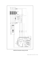
Page 10: ...DER1 digital regulator instruction manual rev 03 pag 10 SCC0158 Three phase sensing 75V 150V...

Page 11: ...DER1 digital regulator instruction manual rev 03 pag 11 SCC0159 Three phase sensing 150V 300V...

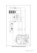
Page 12: ...DER1 digital regulator instruction manual rev 03 pag 12 SCC0160 Single phase sensing 75V 150V...

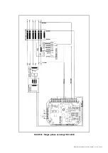
Page 13: ...DER1 digital regulator instruction manual rev 03 pag 13 SCC0161 Single phase sensing 150V 300V...

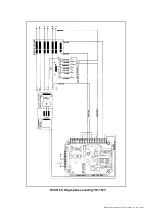
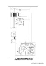
Page 14: ...DER1 digital regulator instruction manual rev 03 pag 14 SCC0202 Single phase sensing 300V 600V...

Page 15: ...DER1 digital regulator instruction manual rev 03 pag 15 SCC0203 Single phase sensing 300V 600V generator in threephase ZIG ZAG connection...

Page 16: ...voltage can be controlled by software as well with the P 19 The excursion range and gain of the remote control can be set independently by software despite the output voltage control device system us...

Page 17: ...protection of up to 20 with respect to the nominal speed value set by the 50 60 jumper if activated or by the 50 50 box in the Configuration menu at 50 Hz the threshold can be calibrated from 40 Hz to...

Page 18: ...6 126 126 18 Step limitation reference 20 20 0 8 19 Vout Reference 6 9 9 0 0 8 20 Stability 6 9 9 16384 16384 8 21 A D A 6 9 9 16384 16384 FG 8 22 4 6 9 9 16384 16384 8 23 2 6 9 9 9000 9000 2 24 2 6...

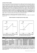
Page 19: ...ltage reaches the limit foreseen for input to which it is applied see Para 8 Remote control of voltage If saturation is enabled in the event of removal of the Vext Pext connection due to accidental op...

Page 20: ...ated voltage tenths of volts 37 Second status word 0 900 Read only Frequency tenths of Hz 38 Third status word 16bit Read only Active alarms 39 Fourth status word 16bit Read only Active configuration...

Page 21: ...cale H on sensing inputs 4 5 9 10 11 12 14 17 and 19 22 between 150 300 Vac scale F There are two ways to set from minimum to maximum value 1 With the VOLT trimmer which must be enabled by the Configu...

Page 22: ...to obtain the desired gain i e parameter P 11 4 coefficient 24 16 The regulator diagram is shown in figure 6 KP KI s Ref Feedback Error PIout figure 6 Regulator Diagram 3 EXCITATION OVERCURRENT 3 1 D...

Page 23: ...nderspeed protection threshold rotating the Hz trimmer counter clockwise if it has been enabled from the Configuration Menu or by entering 0 at parameter P 21 2 Rotate the AMP trimmer completely in th...

Page 24: ...proportionately reduced as indicated in figure 8 Parameter P 23 sets the slope of the voltage frequency curve the default value is 9000 An increase in the value of P 23 involves a greater reduction of...

Page 25: ...ues between 65535 1 and 32768 32767 lower the threshold proportionately to 50 Hz and 60 Hz respectively values between 0 and 32767 raise the threshold proportionately respectively to 60 Hz and 72 Hz r...

Page 26: ...ge a decrease in the value of P 24 will cause a lower reduction in voltage up to the limit of P 24 0 which means that no reduction in voltage will take place WARNING If the voltage is not lowered enou...

Page 27: ...age 5 Excitation Overcurrent APO Reduction of excitation current 6 Underspeed APO V F Ramp 7 Overspeed APO TABLE 12 ALARMS LIST TABLE 13 ALARM FLAGS AT LOCATION L 38 6 5 J 9 6 6 9 J 6J J 5 5 J J 12 1...

Page 28: ...ted short circuit time goes from 0 1 to 25 5 seconds programmable in 100 ms steps then the regulator is blocked after saving DD and TT and signals the STOP status With the time in short circuit set on...

Page 29: ...for which the APO must be activated obtaining a number B Example since it is desired to activate the APO in the case of over voltage and overspeed the formula is B 2 64 66 b Multiply the delay it is...

Page 30: ...serial interfaces available on the DI1 communications unit are RS232 without handshake 3 wires on CN3 connector _____ RS485 two wires half duplex on CN4 connector DTE 1 Tx RTSRx RTS The connection be...

Page 31: ...ector CN1 terminals 1 and 4 1 through a dedicated source AC 40V 15Hz 270V 72Hz or DC 40V 380V 3 Alternatively on connector CN5 terminals 1 and 2 through a completely isolated source in DC 9 14V WARNIN...

Page 32: ...ational parameters reading of stored alarms A standard serial cable may be used with 9 pins SUB D connectors TABLE 18 CONNECTOR CN4 Pin N Description Notes 1 485 A RS485 channel A Insulated 2 485 B RS...

Page 33: ...regulator instruction manual rev 03 pag 33 Fig 12 RS232 connection between one DSR regulator and PC through DI1 digital interface Fig 13 R485 connection between DSR regulators and PC through DI1 digit...

Page 34: ...tor 15 goes from red to green IMPORTANT The communication may take place only if all three of the indicators Connected 16 Com STAT 15 and Com ERROR 14 are green The ADDRESS window indicates the slave...

Page 35: ...tings files to and from the regulator which have the extension dat The list of parameters is shown in table 6 There are three possible options 1 Upload Data The Upload window opens The key Open allows...

Page 36: ...equency protection threshold equivalent to Hz 22 16384 Excitation overcurrent threshold equivalent to AMP 23 9000 V F slope 24 6000 V F slope at start up 25 20 Short circuit time in tenths of a second...

Page 37: ...1 digital regulator instruction manual rev 03 pag 37 Fig 15 DSR Terminal User Interface Fig 16 Configuration Menu 1 3 2 4 6 5 9 8 7 12 14 16 17 15 11 10 13 31 18 19 20 21 22 23 32 33 24 25 26 27 28 29...

Page 38: ...parameters requested from the regulator 9 Activation of updating almost in real time 10 Visualisation of the regulator status voltage frequency active alarms configuration 11 50 60Hz Jumper inserted...

Reviews: