INSTALLATION
SPARTAN IRONWORKER
A-3
© MARVEL MFG. CO., INC. MANUAL
PL/OMiW-2CYL_V2
(08/07)
1.
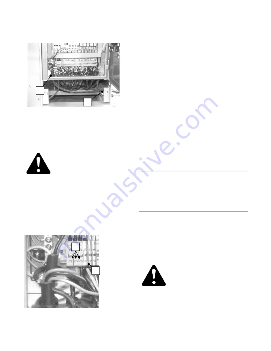
Open the electrical panel door and remove
the panel directly below the door.
The electrical panel door and access panel must be removed
to connect a power cord. The cord is then passed through
the hole in the end of the machine (A) and up into the
electrical enclosure (B). See step 2, below.
Avoid damaging the machine.
Make sure the supply voltage
and phase matches the voltage
the machine has been wired for.
Refer to the data plate on the
electrical enclosure.
2.
Bring a three-phase power cord into the
electrical enclosure through the entrance
hole on the end of the machine (A) and
then up through the hole in the floor of the
electrical enclosure (B).
3.
Connect the power cord's three power
leads to terminals L1, L2, and L3 at the
bottom of the terminal strip (See photo).
The main power leads L1, L2, and L3 (C) connect to the
terminals at the bottom of the terminal strip. The ground
wire connects to the yellow and green terminal next to the
power lead connections (D).
4.
Attach the power cord's grounding wire to
the grounding terminal (D, see photo).
The importance of a properly grounded
machine cannot be over emphasized - both for
the safety of the operator and the dependable
operation of the machine.
The machine must be grounded,
by a qualified
electrician
, in conformance with:
a.
National Fire Protection Association
(NFPA) No. 79, "Electrical Standard for
Metal Working Machine Tools".
b.
National Fire Protection Association
(NFPA) No. 70, "National Electrical
Code".
c.
The prevailing national, state, and local
electrical codes.
LUBRICATION
The lubrication points and intervals must be
checked before operating the saw. Refer to
"Lubrication", page J-2.
ELECTRICAL CHECK
IMPORTANT: Read steps 1 through 6 before
performing this electrical check.
This electrical check ensures the leads of the
power cord are properly connected.
Avoid damaging the machine.
Make sure the hydraulic fluid
level is correct before operating
the
machine.
Refer
to
"Checking the Hydraulic Fluid
Level", page J-2.
1.
Set the following switches as indicated:
•
Auto / Manual switch - Manual
•
Turn the Emergency Stop pushbuttons
clockwise to reset them.
CAUTION
CAUTION
B
A
C
D


