background image

is the E and N coordinates that you can see in the upper left corner. It is important to keep in mind
that the measuring point on the bucket is above the desired starting point for length/cross slope.

Temporary profile

Menu > Project > Temporary profile

Toggling the ‘Profile’ option turns the temporary profile on or off, while its settings are kept
persisted.

There are two options for moving the profile, respectively ‘Set profile here’ and ‘Set profile &
direction here’. The first option horizontally displaces the profile and positions the middle of its
centerline at the tool point. In addition, the latter option also rotates the profile according to the
heading of the bucket/attachment.

Adjusting the ‘Slope’ will tilt the profile along its baseline.

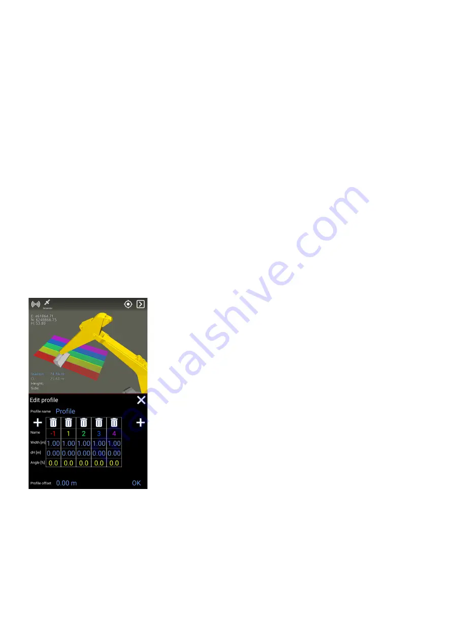
Under ‘Edit profile’ you can change the profile’s contours, by adding and removing surfaces as well
as changing the width and slopes of the surfaces. Changing slopes can be done, either by
specifying the height difference between two surfaces or by specifying the percentage slope
between them. Also, you can specify a height offset for the profile, where the baseline is indicated
by a gray line in the 3D View.

The profile can be rotated by using ‘Edit direction’. North corresponding to 0 (zero) degrees. The
feature ‘Get direction from tool’ will align the profile according to the bucket/attachment.

As an alternative to going via the menu, you can jump to this feature by tapping the profile in the
3D View.

Change offset

Menu > Project > Change offset

Makin' 3D User guide 2.18, 1st edition, May 2022 © Copyright 2021, Makin AS

36

Summary of Contents for Stakeout Makin' 3D

Page 1: ...User guide Stakeout Version 2 18 Makin 3D User guide 2 18 1st edition May 2022 Copyright 2021 Makin AS 1...

Page 2: ...nt are subject to change without prior notice Every precaution has been taken in the preparation of this manual Nevertheless Makin assumes no responsibility for errors or omissions or any damages resu...

Page 3: ...6 ISO 13766 2006 9 Tablet buttons and light indicators 10 Controlling basic tablet functionality 11 Programming the physical tablet buttons 12 Tablet Panasonic FZ A3 connections 12 Tablet Juniper Mes...

Page 4: ...e color 39 Show maps 40 Show other systems 40 Show logged points 41 Show textures 41 Auto hide quick keys 41 Reverse quick keys 42 Transparent surfaces 42 Dark theme 42 Wireframe 43 Change screen 43 V...

Page 5: ...ction source 57 Radio 57 Ntrip 58 Heading method 58 Bluetooth 59 Connecting and pairing bluetooth 59 Pole 59 Chat 60 Status 61 7 Troubleshooting 63 8 Appendix 64 GNSS limitations 64 Demo mode 65 Netwo...

Page 6: ...y We recommend that the operator of the machine frequently checks the positioning against a known point on every job site See chapter 7 How to check calibration 1 3 Storage Keep the equipment safe whe...

Page 7: ...ch events is important to ensure an optimum result Warranty For further details visit www Makin3D com for more information 2 2 Limitations The product is intended as a control tool for machine operato...

Page 8: ...eement between you and Makin we refer you to visit Makin s website www Makin3D com 2 5 Software update Software will automatically and frequently be updated and users will get a notification on the sc...

Page 9: ...as other equipment The directive also governs the immunity of such equipment to interference and seeks to ensure that this equipment is not disturbed by radio emissions when used as intended 3 4 2011...

Page 10: ...f button 6 Volume down 2 Power indicator No light System is off Green light System is on Blinking green light Tablet 7 Not in use Button can be programmed more info below Makin 3D User guide 2 18 1st...

Page 11: ...board app Button can be programmed more info below 5 Volume up Additionally screenshots can be taken by pressing the On Off button and Volume down simultaneously holding down buttons 1 and 6 for about...

Page 12: ...ons Through an app called UserButtonManager some of the physical buttons of the tablet can be easily programmed These are called A1 A2 A3 and Rotate Lock in the app and correspond respectively to butt...

Page 13: ...station connector for data and power transmission 6 SuperSpeed USB A 3 0 3 Micro SIM card for broadband internet on both tablet and GNSS receiver 7 Mini jack audio output 4 USB C 8 Micro SD for exten...

Page 14: ...Docking station connector for data and power transmission 4 USB C 4 2 Software How to turn the system on Turn on your Makin 3D system by pressing the on off button on the tablet Android will start up...

Page 15: ...ee 5 1 under Open or create a project Elements of the runscreen Makin 3D has many different screens to choose between Below is an explanation of one that contains most of the visual features available...

Page 16: ...of the slope in the main direction of the tool point The arrow indicates the vertical distance to the selected height reference The arrow will change color depending on the distance to the target Tap...

Page 17: ...Easting Northing and Height coordinates 8 Change the height offset according to the current reference e g the specified plane or the loaded model file 5 Tap any element in the loaded 3D model to brin...

Page 18: ...mote support case where you will be notified Bring your machine back to the center of your screen after zooming and panning Placed in the upper right corner Tap for change of screen depending on the w...

Page 19: ...and name of the bucket are shown on the icon s label Tap to access the Bucket dialog Menu from where you can access all features of the system Makin 3D User guide 2 18 1st edition May 2022 Copyright 2...

Page 20: ...or referencing lines and surfaces in more complex 3D models Open or create a project Menu Project Open project To open an existing project In Project tap Open project to see all the projects stored T...

Page 21: ...te and observation format KOF New projects are stored in LandXML format Note When Makin 3D reaches 170 MB data in size a warning will pop up informing you that the project is big This can reduce perfo...

Page 22: ...the project 4 Green is used for elements that may reference the height Press to select as reference Long press will deselect all other height references selected 2 White means an element is visible an...

Page 23: ...es selected As an alternative to going via the menu you can also find this feature in the Quick Keys menu or by selecting any element in the 3D model Makin 3D User guide 2 18 1st edition May 2022 Copy...

Page 24: ...Folders In the references example below we see all the data that has been entered on a road parcel Makin 3D User guide 2 18 1st edition May 2022 Copyright 2021 Makin AS 24...

Page 25: ...height reference alert reference for a folder you enable the option for all models in the entire folder For example if you have many road models you may want to open the folder with the small gray ar...

Page 26: ...u can select specific data to make visible and choose what to actively work against To get an indication towards the different model files side and or height must be activated As with viewing you do t...

Page 27: ...bled will automatically be used Height references are typically surfaces but also lines and points can be selected for height calculations Alert reference Alert references are geometries used for aler...

Page 28: ...eference menu or directly in the run screen 1 Select an object by pressing the object name or directly on the visualized object in the run screen Press the lock icon to lock to the selected reference...

Page 29: ...es they are not placed in height 0 00 meters They are moved closer to the project right below the active 3D references lowest point These files are handled dynamically so whenever a 3D reference is ac...

Page 30: ...up will appear with all the stakeout information for the selected line The stakeout menu can be freely moved around on the tablet Makin 3D User guide 2 18 1st edition May 2022 Copyright 2021 Makin AS...

Page 31: ...al distance between tool point and selected reference Measured perpendicular to the line 8 Horizontal length of stakeout line 2 Vertical distance between tool point and selected reference 9 Length of...

Page 32: ...l be negative to the closest end point 12 Length of line segment 6 Name of selected stakeout line 13 Height difference of the line segment 7 Type of selected reference arc circle line polyline road li...

Page 33: ...under User model Points Create line from points From References tap and then Line You can create lines between existing points either from a design model or from points you have created yourself The...

Page 34: ...u want You can also adjust the height offset of the whole profile Geodetic systems Menu Project Geodetic system Only in rare cases should the machine operator be concerned about selecting the correct...

Page 35: ...dition of taking the reference height offset into account When the plane is active you can tap the visual part of the plane to quickly change its values When you no longer need this feature it is impo...

Page 36: ...ent Adjusting the Slope will tilt the profile along its baseline Under Edit profile you can change the profile s contours by adding and removing surfaces as well as changing the width and slopes of th...

Page 37: ...a machine s height to match the height on the project you are working on Even if a machine is correctly calibrated the height measured on a toolpoint of the application can differ from the height on a...

Page 38: ...djust the project offset with the buttons which will increment or decrement the value by 1 cm 4 A project offset is calculated and visible in the project menu When you have a project offset the icon w...

Page 39: ...lt color scheme of Makin 3D In some situations it gives a better overview using the colors of the model file and will make it easier to separate elements in a complex file If file color is not enabled...

Page 40: ...are only shown on elements of the 3D model marked as a height reference Note In the 3D View the map will be seen in a perspective view If you want to see it straight from above use the Top View instea...

Page 41: ...d of using solid colors you can have textures shown This is only possible for road geometry Auto hide quick keys Menu Display Auto hide quick keys Auto Hide Quick Keys will hide the quick keys at the...

Page 42: ...y Transparent surfaces Hide the surfaces to be able to see lines and points beneath them Note Surfaces with textures will not be transparent Warning Reference selection is not visible when transparent...

Page 43: ...show the edges of the triangles and might improve the visibility Change screen Menu Display Change screen This option is to change the working screen Change screen is also accessible by tapping the i...

Page 44: ...Scroll down to View settings It is possible to set this individually for a work situation or when you touch the screen You can also choose individual settings for runscreens with 3D View or Top View M...

Page 45: ...the reference the job is well done Red is an indication of excavating too deep into the ground The tolerance is actually an expression for when to ignore the warning when you are far below the referen...

Page 46: ...ying Too close If you are in the Danger area you will get a Danger notification also an alarm will sound if turned on Choose any of the 3 options Show Warning Danger Change the distance you want to th...

Page 47: ...automatically changed and saved Angle unit Menu Settings Angle unit Set angle unit Tap to choose the angle unit The angle unit is automatically changed and saved Sound Volume Menu Settings Sound volum...

Page 48: ...cts on the server Tap to enable or disable 5 4 Logging As built Menu logging Point logging can also be accessed by long pressing the shortcut in the run screen The 10 most recently used point codes ar...

Page 49: ...ogging The confirmation pop up will disappear after approximately 10 seconds The last used point code will remain active until it s changed Own log codes Menu Point logging Other codes Own codes You c...

Page 50: ...new line you must log the starting point of the line or select an existing point in the project When a point is selected you press the log line icon in the reference menu to enable the log line mode...

Page 51: ...ode ID PointCodeName NAME GROUP ID NAME PointCode ID PointCodeName NAME GROUP ID NAME DESCRIPTION PointCode ID PointCodeName NAME The point code list must be made in the UTF 8 format If the pointcodes...

Page 52: ...Select Other Codes Common codes Makin 3D User guide 2 18 1st edition May 2022 Copyright 2021 Makin AS 52...

Page 53: ...Here you can select a point code from the list and then log the point Makin 3D User guide 2 18 1st edition May 2022 Copyright 2021 Makin AS 53...

Page 54: ...he system name on the Cloud PDOP Dilution Of Precision indicates how errors in measurement will affect the absolute position calculation Dop can be calculated in different variants HDOP VDOP PDOP TDOP...

Page 55: ...eightrefName Height reference name Shows the name of the specific reference inside the reference file used as active height reference when point was logged ToolPoint Shows which toolpoint was used to...

Page 56: ...ng dialog In this dialog you can choose which criteria you want to sort by Press the button to activate or deactivate the criteria You can also change the order you want to sort by This is done by pre...

Page 57: ...t type of correction source being used Tap Correction source to change it Tap your choice of NTRIP or UHF Choose UHF if you use a radio to connect to the correction signal Tap Frequency to set the fre...

Page 58: ...nt on the server has a unique username that Makin needs to log in to the server Ntrip password Every Ntrip account on the server has a unique password that Makin needs to log in to the server Ntrip mo...

Page 59: ...to the GNSS icon in the top With this icon connection to the GNSS device still waiting to be established this might take 2 3 minutes when all LED s on the GNSS device is turned on with a solid light...

Page 60: ...the project you are working on You will see all office personnel and coworkers from your company or project This depends on the structure made by your management Tap a contact from the list to begin...

Page 61: ...led system information Tap GNSS to see the connection status and your location Tap Sensors to see detailed sensor information Version is the current Makin 3D software version of the Android app runnin...

Page 62: ...IB 1 version is the firmware version of the interface box connecting all the sensors to the system Makin 3D User guide 2 18 1st edition May 2022 Copyright 2021 Makin AS 62...

Page 63: ...Error message Possible cause Possible Solution If you cannot solve the problem using the advice found in the above table contact your reseller Makin 3D User guide 2 18 1st edition May 2022 Copyright...

Page 64: ...ng near forest and mountain areas interference could block the signal from one or more satellites and cause poor precision Reflections could also occur Makin 3D will inform you if there are not enough...

Page 65: ...in Odense S n N Move forward backward b B Turn to the left right m M Turn to the right left space Start stop automatic driving s S Move forward backward on the centerline Raise machine lower machine r...

Page 66: ...1 Roll 2 Pitch 3 Rotate tracks 4 Boom 5 Stick 6 Bucket 7 Tilt 8 Rotor Makin 3D User guide 2 18 1st edition May 2022 Copyright 2021 Makin AS 66...

Page 67: ...run demo system Makin Win you must verify with the local network administrator that the following requirements are fulfilled to connect to Makin Cloud Outbound traffic on port 80 8008 10000 12000 Acce...

Reviews: