


13
© 2010 Magnum Energy, Inc.
3.0 Setup
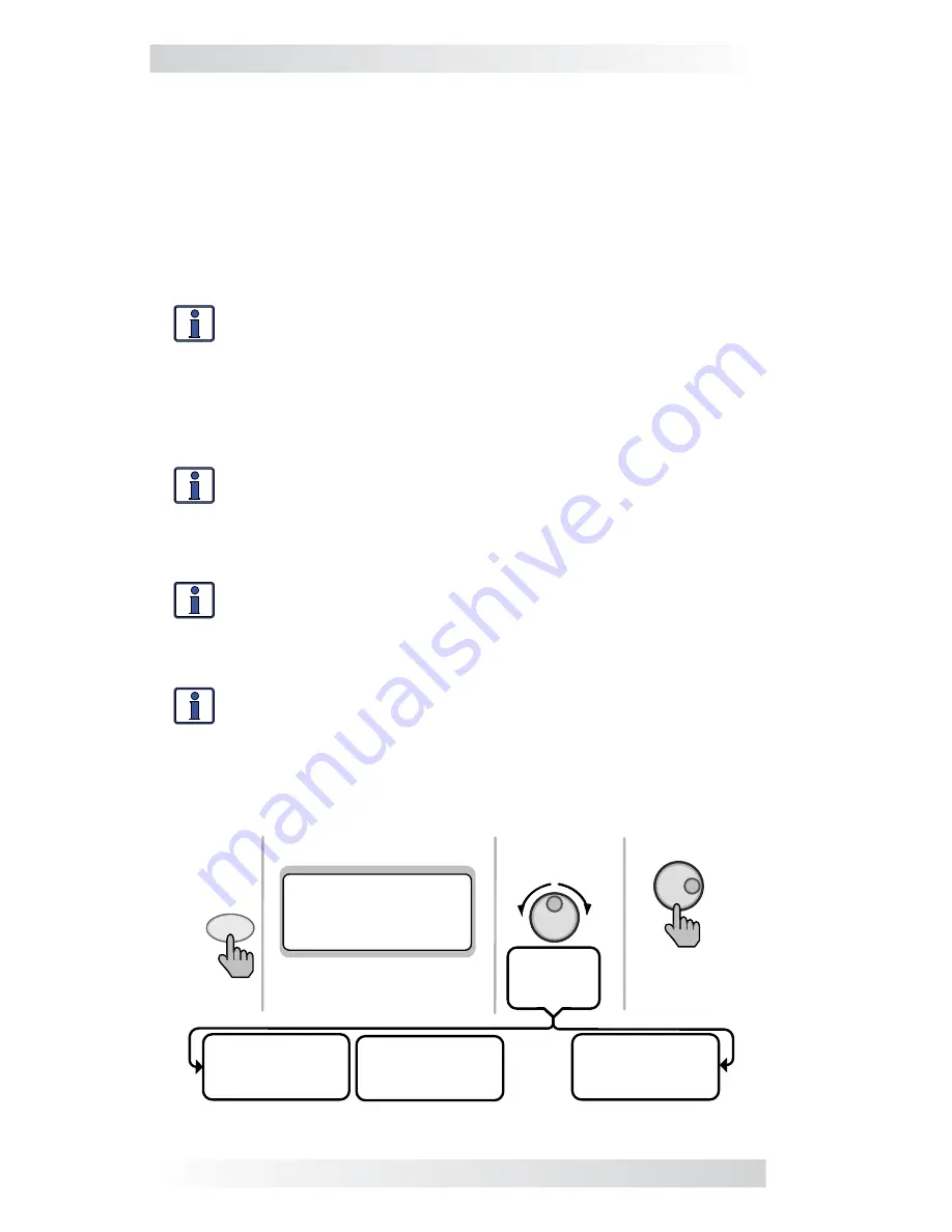
Figure 3-2, PORT Button
Press to edit
setting
Press
PORT
Rotate to
desired
selection:
MS4024PAE
Inverting
25.6 VDC 10 ADC
P1 INV Home
Top line shows status
Bottom line shows current
port. Press PORT button to
access next port.
OR rotate to
next port
MS4024PAE
Inverting
25.6 VDC 20ADC
System INV Home
Auto Gen Start
Ready 0.0 Hrs
25 .6 VDC 70F
P 1Acc AGS Home
… ......
MS4024 PAE
Inverting
25 .6 VDC 10 ADC
P3 INV Home
Info:
You must be on a Home screen menu (“
Home”
appears
in bottom right corner of router’s LCD display) in order for the
PORT button to scroll through all the active ports. If you are not
on a Home screen, pressing the PORT button will only display
devices that are related to the screen you are currently viewing
(only true for METER, SETUP, and TECH button menus, PORT
button does not work from CTRL button menus).
Info:
Pressing and holding down the METER button for 3-seconds
takes you back to the System Home screen from any menu.
Any remaining open ports may be used to connect Magnum accessories such
as an ME-AGS-N, ME-BMK/ME-BMK-NS, and an ME-RC or ME-ARC remote.
Info:
You can connect a maximum of four inverter/chargers
to a router. If the maximum number of inverter/chargers are
connected, two open ports remain. If more ports are needed
for accessories, the Network port on each inverter/charger may
also be used for accessories.
Info:
When an accessory is plugged into a communication port
on the router, the PORT button displays the accessory as the
corresponding port (i.e.,
Port 5
would show “
ME-AGS-N”
). If an
accessory is plugged into the Network port on one of the parallel
inverter/chargers, the PORT button will display the accessory
as “
P#Acc
” (i.e., a ME-AGS-N plugged into a parallel inverter/
charger that is plugged into Port 1 would display as “
P1Acc”
).
3.2 Router Pushbuttons and Menu Items
The
fi
ve pushbuttons (PORT, CTRL, METER, SETUP, and TECH) located beneath
the LCD screen allow the inverter/charger system to be con
fi
gured to your
speci
fi
c preferences. These pushbuttons also allow you to access menu items
that can help with monitoring and troubleshooting your system.
3.2.1 PORT Button
The PORT button scrolls between the six communication ports on the bottom
of the router. Each parallel inverter/charger must be connected to a commu-
nication port in order to be programmed and to display status info.


