


Installation
4-4
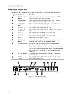
RS-232 Computer (AVM-510A)
This is used for a direct connection to a computer. The computer can be running Logbook Software or
communication software to control the AVM-510A from a remote location.
RS-232 Modem (AVM-510A)
This is used for a direct connection to a modem or printer. When connected to a modem, the AVM-
510A can be controlled over telephone lines using a computer running Logbook Software. When
connected to a printer, waveforms and vectors can be printed to paper.
Configuring the Inputs
As you become familiar with the MM-410/AVM-510A you will learn how flexible it is. The MM-
410/AVM-510A lets you select a variety of settings to fit your specific needs. However, an important
thing to remember is the format of the three signal inputs: Input A:, Input B:, and an external reference
(see Figures 2-2 and 3-2). All inputs automatically switch between 525/60 and 625/50 formats.
•
Input A:
Single loop through composite (NTSC or PAL) input signal (CPST-1).
•
Input B:
Single loop through, configurable composite (NTSC or PAL), 3-wire component, or
S-video input signal (CPST-2, SMPTE/EBU, BETA, GBR (RGB), MII).
•
The external reference is a switchable loop-through composite 525/625 studio reference timing
input (optional).
You can select Input A:, Input B:, or both Input A: and Input B: using the
Input
button on the front
panel. You can also select an External Reference (Ext Ref) by pressing the
Blue
(2nd) button and
then the
Field Sel
button (
Field Select
for the AVM-510A).
Refer to Chapter 5, “Front Panel Operation,” for more information about configuring the
MM-410/AVM-510A using the front panel buttons.
Saving Settings in Memory
After you configure the MM-410/AVM-510A, you need to save it in memory. The following
procedure explains how to store an MM-410/AVM-510A configuration in a memory location using
the Config (Configure) menu.
1.
Select the desired signal input by pressing the
Input
button or through the Config menu options.
2.
Configure the MM-410/AVM-510A for a desired mode.
3.
Using the Vertical and Horizontal Position knobs, center the display.
4.
Press the
Config
button to access the Config menu.
5.
Using the arrow buttons, select MEMORIES and then press the
Enter
button.
6.
Using the
Arrow
buttons, select STORE MEMORY.
7.
Using the knob, select the desired memory location (1 through 10).
Summary of Contents for MM-410
Page 16: ...About This Manual 1 4 Notes...
Page 34: ...Installation 4 6 Notes...
Page 48: ...Front Panel Operation 5 14 Notes...
Page 102: ...Viewing Waveforms Vectors and Pictures 7 30 Notes...
Page 126: ...Automatic Measurement AVM 510A 9 20 Notes...
Page 148: ...AVM 510A C For Component Measurements 12 4 Notes...
Page 158: ...Connector Pinouts B 4 Notes...
Page 162: ...Calibration D 2 Notes...