


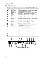


Product Overview (AVM-510A)
3-4
Power Switch
Powers the AVM-510A on and off.
Mode Buttons
The
Mode
buttons and the
Blue
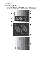
button determine what the monitor displays: Wfm, Mix,Vector,
Picture, AutoMeas (Automeasure), or Memory Recall.
Refer to Chapter 5, “Front Panel Operation,” for more information about configuring the
AVM-510A using the front panel buttons.
Input Button
This button lets you choose three signal inputs (Input A: only, Input B: only, or both Input A: and
Input B:).
Input Signal LEDs
Two Input Signal LEDs (Input A: only, Input B: only, or both Input A: and Input B:) light in
conjunction with the three
Input
button selections.
Refer to Chapter 5, “Front Panel Operation,” for more information about configuring the
AVM-510A using the front panel buttons.
Display Button
This button lets you choose between a Single, Alternate, or Parade view of component signals.
Display Button LEDs
Three Display LEDs (Single, Alternate, and Parade) light in conjunction with the three
Display
button selections.
Refer to Chapter 5, “Front Panel Operation,” for more information about configuring the
AVM-510A using the front panel buttons.
Vertical Position Knob, LEDs, and Buttons
The vertical section of the front panel includes four buttons and one knob: Position (
Wfm Pos
),
Vertical Magnification (
Mag
), Filter (
Filter
), and Split Screen (
Split Screen
), and a vertical
positioning knob for vertical control options.
Summary of Contents for MM-410
Page 16: ...About This Manual 1 4 Notes...
Page 34: ...Installation 4 6 Notes...
Page 48: ...Front Panel Operation 5 14 Notes...
Page 102: ...Viewing Waveforms Vectors and Pictures 7 30 Notes...
Page 126: ...Automatic Measurement AVM 510A 9 20 Notes...
Page 148: ...AVM 510A C For Component Measurements 12 4 Notes...
Page 158: ...Connector Pinouts B 4 Notes...
Page 162: ...Calibration D 2 Notes...