Contents
ix
F. Glossary of Terms
.......................................................................................................................F-1
G. Applications
................................................................................................................................. G-1
Figures
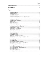
2-1. MM-410 Front View................................................................................................................. 2-3
2-2. MM-410 Rear View.................................................................................................................. 2-6
3-1. AVM-510A Front View ............................................................................................................ 3-3
3-2. AVM-510A Rear View ............................................................................................................. 3-6
4-1. MM-410/AVM-510A Rack Installation (AVM-510A Shown) .............................................. 4-2
5-1. MM-410 Front View................................................................................................................. 5-2
5-2. AVM-510A Front View ............................................................................................................ 5-3
5-3. Monitor Display Explanation................................................................................................... 5-4
5-4. Input Screen ............................................................................................................................ 5-10
5-5. Color Limits Screen................................................................................................................ 5-11
6-1. Config Menu Options............................................................................................................... 6-2
6-2. A and B Measurements (Composite NTSC) ........................................................................... 6-8
6-3. A and B Measurements (Composite PAL) .............................................................................. 6-9
7-1. Basic Waveform Display .......................................................................................................... 7-2
7-2. 1H Sweep Rate (A: 525 CPST) ............................................................................................... 7-3
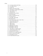
7-3. Added Marks Box Locations ................................................................................................... 7-4
7-4. Waveform Limit Lines at 70 and –10 IRE............................................................................... 7-5
7-5. PAL Volts Graticule .................................................................................................................. 7-6
7-6. PAL Percent Graticule .............................................................................................................. 7-6
7-7. Line Select Indicator................................................................................................................. 7-8
7-8. 2F Sweep, Highlighting Lines 17 and 18................................................................................ 7-9
7-9. 2H Sweep, Line Select on Lines 17 and 18, Even Fields ....................................................... 7-9
7-10. Luma Filter on Bars.............................................................................................................. 7-10
7-11. Chroma Filter........................................................................................................................ 7-11
7-12. Parade of Filters .................................................................................................................... 7-11
7-13. Beta Component Waveform and Vector............................................................................... 7-12
7-14. Beta Signal in Alternate with B-Y and R-Y Raised............................................................ 7-13
7-15. 525 Beta Signal, Parade Mode............................................................................................. 7-13
7-16. Composite Vector.................................................................................................................. 7-16
7-17. Component Waveform and Vector ....................................................................................... 7-16
7-18. Composite Waveform and Vector at 1H Sweep .................................................................. 7-16
7-19. PAL Vector Display .............................................................................................................. 7-18
7-20. PAL Vector with +V Switch................................................................................................. 7-18
7-21. Two Composite Waveforms (Alternate) .............................................................................. 7-20
Summary of Contents for MM-410
Page 16: ...About This Manual 1 4 Notes...
Page 34: ...Installation 4 6 Notes...
Page 48: ...Front Panel Operation 5 14 Notes...
Page 102: ...Viewing Waveforms Vectors and Pictures 7 30 Notes...
Page 126: ...Automatic Measurement AVM 510A 9 20 Notes...
Page 148: ...AVM 510A C For Component Measurements 12 4 Notes...
Page 158: ...Connector Pinouts B 4 Notes...
Page 162: ...Calibration D 2 Notes...


