


Automatic Measurement (AVM-510A)
9-7
Setting Automeasurement Limits
The AUTOMEASURE/AUTO MEAS SET menu lets you set measurement limits over very wide
ranges. You can set different limits for Input A: and Input B:, for 525 and 625 systems, and for
different component systems.
After setting the limits for any measurement set, the green (safe) area changes in the bar graph. You
can set the limits for each parameter, and anything else you set is saved for that measurement set on
that input for that system (525 or 625).
There are separate limits for Input A: and Input B:, separate limits for 525 and 625 systems (even for
the same input), and separate limits for each of the measurement sets as listed in the following table.
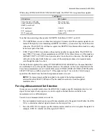
List of Different Measurement Sets
(There is a different set of limits for each of these combinations)
525 Signals
625 Signals
Input A:
Input B:
Input A:
Input B:
System video
System video
System video
System video
Color setup
Color setup
Colour setup
Colour setup
Frequency response
Frequency response
Frequency response
Frequency response
Non-linear (N & T)
Non-linear (N & T)
Non-linear (N & T)
Non-linear (N & T)
Transmitter (T)
Transmitter (T)
Transmitter (T)
Transmitter (T)
You can set the limits when you are viewing the automeasure screen or when any other display is
active. To set the limits for any measurement set:
1.
Select an Input A: or Input B: signal input.
NOTE:
If Input B: is selected, make sure it is configured for composite or S-video. There
is no measurement set for component signals in the AVM-510A.
2.
Press the
Mesmnt
button.
3.
Select SELECT SET and then press the
Entr
button.
4.
Select the appropriate measurement set and then press the
Entr
button.
5.
Select MEASURE LINE and then turn the knob to select the line where the test signal will be
found. Press the
Field Select
button if you need to switch fields.
6.
Push the down
Arrow
button twice to highight LIMITS, which has the name of the measurement
set and the input letter.
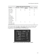
7.
Press the
Entr
button.
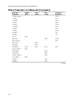
Four columns now appear on the display. On the left is the MEASUREMENT parameter. The other
three columns show the minimum and maximum limits and the nominal values. Note that some
parameters have a maximum only.
8.
Using the
Arrow
buttons, move the cursor up and down to highlight the desired parameter.
Summary of Contents for MM-410
Page 16: ...About This Manual 1 4 Notes...
Page 34: ...Installation 4 6 Notes...
Page 48: ...Front Panel Operation 5 14 Notes...
Page 102: ...Viewing Waveforms Vectors and Pictures 7 30 Notes...
Page 126: ...Automatic Measurement AVM 510A 9 20 Notes...
Page 148: ...AVM 510A C For Component Measurements 12 4 Notes...
Page 158: ...Connector Pinouts B 4 Notes...
Page 162: ...Calibration D 2 Notes...