


AVM-510A Option T (For Transmission Monitoring)
11-10
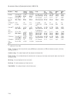
Memory Table
AVM-510A-T Memory Locations
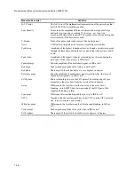
Memory
Input/Format
Description
Other Items
1
A Composite
Waveform, two line display
Nonlinear measurement set,
line 17 field 1
2
A Composite
Picture with save title marks
System video measurement
set, line 35 field 1
3
A Composite
Waveform and vector overlayed
4
A Composite
Vector display
5
A Composite
Automeasure, transmitter measurement set
line 17 field 1
6
A Composite
Split screen of picture inset with waveform and
vector
7
A Composite
Differential gain
Nonlinear measurement set,
line 17 field 1
8
A Composite
Differential phase
Nonlinear measurement set,
line 17 field 1
9
B Beta
ICPM at 2
°
/division
Transmitter measurement set
line 17 field 1
10
B Beta
ICPM at 6
°
/division
Transmitter measurement set
line 17 field 1
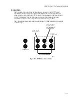
All settings are saved under each memory location.
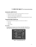
Applications
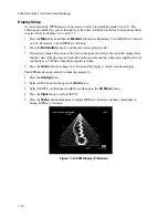
Differential Gain/Phase
Differential gain is the luminance interaction on the gain of the chrominance. Differential
phase is the luminance interaction on the phase of the chrominance. Both can be tested with a
modulated staircase or ramp signals. There are specified VIT signals that include 5 step
modulated stairsteps.
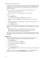
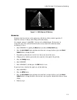
ICPM
ICPM mode is described as the unwanted carrier phase change due to the signal level change in an
amplitude modulated vision signal. On a home receiver with envelope detectors where the inter-
carrier mixing of sound and vision, ICPM in the vision signal decreases the audio signal to noise ratio
and be heard as audio disturbances. These disturbances are commonly known as inter-carrier buzz.
ICPM can be monitored with the in-phase video (I) and the quadrature phase video (Q) outputs of a
television demodulator operating in the synchronous detection mode. The typical video signal is a
non-modulated staircase or luminance ramp signal.
The Magni AVM-510A-T accepts the I and Q signals from a broadcast television demodulator and
provides a standard ICPM vector display either in full field or individual line select mode.
Resolutions of 6°/division, for initial systems set up, and 2°/division, for narrower range monitoring
are provided.
Summary of Contents for MM-410
Page 16: ...About This Manual 1 4 Notes...
Page 34: ...Installation 4 6 Notes...
Page 48: ...Front Panel Operation 5 14 Notes...
Page 102: ...Viewing Waveforms Vectors and Pictures 7 30 Notes...
Page 126: ...Automatic Measurement AVM 510A 9 20 Notes...
Page 148: ...AVM 510A C For Component Measurements 12 4 Notes...
Page 158: ...Connector Pinouts B 4 Notes...
Page 162: ...Calibration D 2 Notes...