


Command Codes (AVM-510A)
E-6
AVM-510A to PC
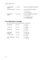
This section describes the data sent from the AVM-510A to a PC. Note that this data might be
requested by the PC or it might arrive at the PC unsolicited.
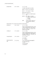
STATUS
INFORMATION
‘S’H0H1H2H3H4H5
H6H7H8H9H10<CR>
Note: A ‘b’ in front of a bit indicates that it
is a 3D button. A ‘l’ in front of a bit indicates
that it is an LED status. An ‘m’ in front of a
bit indicates that it is a Menu item status.
H0
b bit0 wfm mode active
b bit1 vector mode active
b bit2 picture mode active
b bit3 automeasure mode active
H1
b bit0 split screen active
b bit1 HMag active
b bit2 VMag active
b bit3 line select active
H2
b bit0 variable gain active
b bit1 vector phase active
l bit2 ext ref on
l bit3 LED A on (Input A:)
H3
l bit0 LED B on (Input B:)
l bit1 LED single on
l bit2 LED alternate on
l bit3 LED parade on
H4
l bit0 LED luma on
l bit1 LED chroma on
l bit2 LED parade (filter) on
l bit3 LED 1H on
H5
l bit0 LED 2H on
l bit1 LED 2F on
l bit2 LED 1 on (wfm pos)
l bit3 LED 2 on
H6
l bit0 LED 3 on
m bit1 clamp fast
m bit2 bowtie on
m bit3 line select 15 line mode on
H7
m bit0 +V switching on
m bit1 100% color bars mode
m bit2 wide (VCR) lock on
m bit3 SC/H phase display on
Summary of Contents for MM-410
Page 16: ...About This Manual 1 4 Notes...
Page 34: ...Installation 4 6 Notes...
Page 48: ...Front Panel Operation 5 14 Notes...
Page 102: ...Viewing Waveforms Vectors and Pictures 7 30 Notes...
Page 126: ...Automatic Measurement AVM 510A 9 20 Notes...
Page 148: ...AVM 510A C For Component Measurements 12 4 Notes...
Page 158: ...Connector Pinouts B 4 Notes...
Page 162: ...Calibration D 2 Notes...