R
GRAFIK Eye
®
QS System Installation and Operation Guide 5
• System communication uses Class 2 /
PELV low-voltage wiring.
• Follow all local and national electrical
codes when installing Class 2 / PELV
wiring with line voltage/mains wiring.
• Each terminal accepts up to two 1,0 mm
2
(#18 AWG) wires.
• Total length of control link must not
exceed 610 m (2 000 ft.).
• Make all connections in the control unit’s
wallbox.
• A QS system can have up to 100 zones
and 100 devices (see table below).
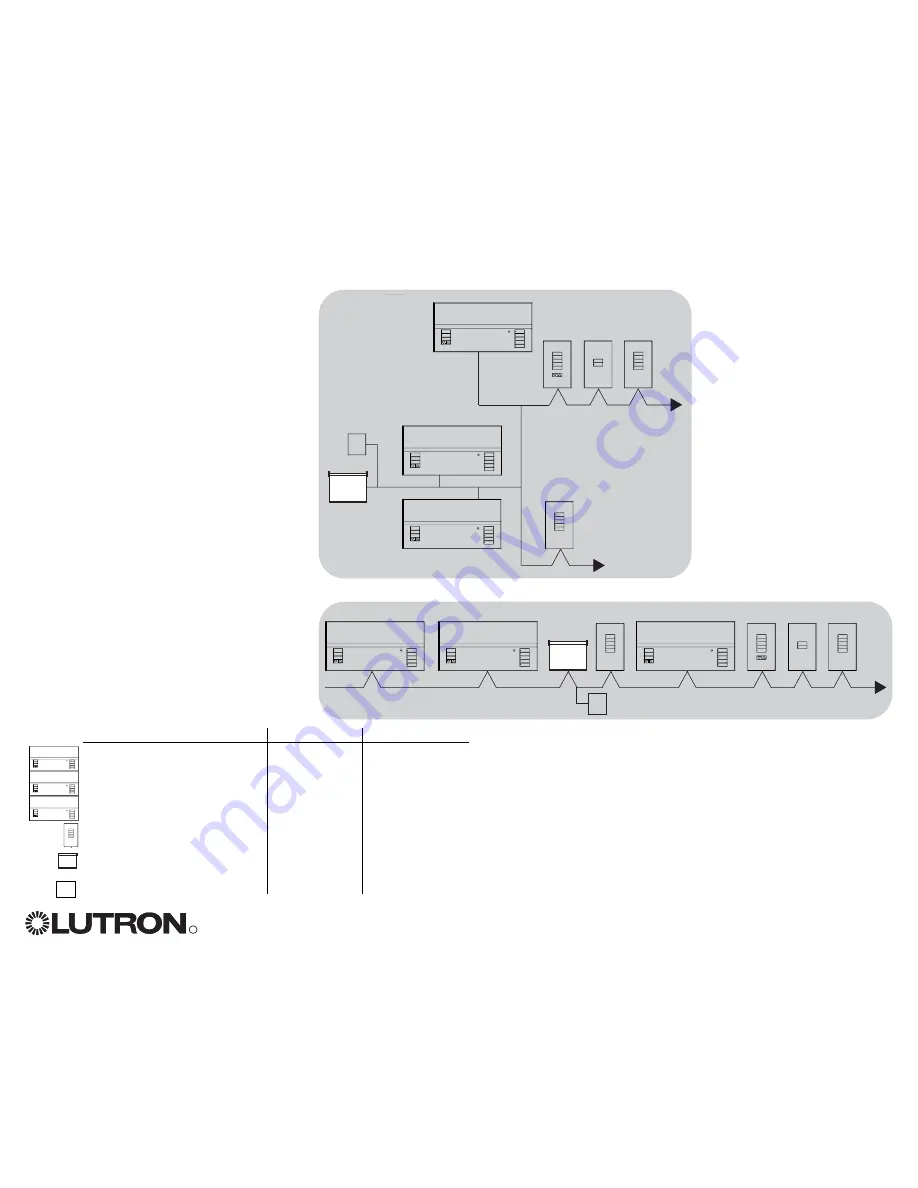
• Wiring can be T-tapped or daisy-chained.
• Wire sizes:
- Two 1,0 mm
2
(#18 AWG) conductors for
control power.
- One twisted, shielded pair of 1,0 mm
2
(#22 AWG) for data link.
- Cable is available from Lutron:
GRX-CBL-S-500 (non-plenum)
GRX-CBLP-S-500 (plenum rated).
Check compatibility in your area.
LUTRON
LUTRON
LUTRON
LUTRON
LUTRON
LUTRON
LUTRON
GRAFIK Eye
QS
Sivoia
QS
seeTouch
QS
LUTRON
LUTRON
LUTRON
LUTRON
LUTRON
LUTRON
LUTRON
Daisy-Chain Wiring Example
T-Tap Wiring Example
GRAFIK Eye
QS
Sivoia
QS
QS smart
power
supply panel
QS smart power
supply panel
seeTouch
QS
QS System Low-Voltage Control Wiring
System Limits
QS Device
Zone Count
Device Count
3-zone QS
3
1
4-zone QS
4
1
6-zone QS
6
1
seeTouch QS
0
1
Sivoia QS 1
1
QS smart power supply panel
0
1
LUTRON
LUTRON
LUTRON
LUTRON


