background image

®

GRAFIK Eye

®

 QS Control Unit Installation and Operation Guide   18

Zone Setup (continued)

Load Type Notes

•  All electronic low-voltage 

(ELV) lighting used with an 

interface must be rated for reverse 

phase control dimming. Before 

installing an ELV light source, 

verify with the manufacturer that 

their transformer can be dimmed. 

When dimming, an ELV interface 

(such as the PHPM-PA-DV-WH) 

must be used with the control 

unit.

•  For all DMX or RGB/CMY DMX 

lighting, an external DMX interface 

(such as the QSE-CI-DMX) must 

be used with the control unit.

Zone ratings:

• Not all zones must be connected; 

however, connected zones must 

have a minimum load of 40 W.

• Maximum loads:

  10 A per unit  

500 W per zone.

• Maximum total lighting load for a 

magnetic low-voltage (MLV) load 

is 500 VA / 400 W.

LUTRON

LUTRON

LUTRON

LUTRON

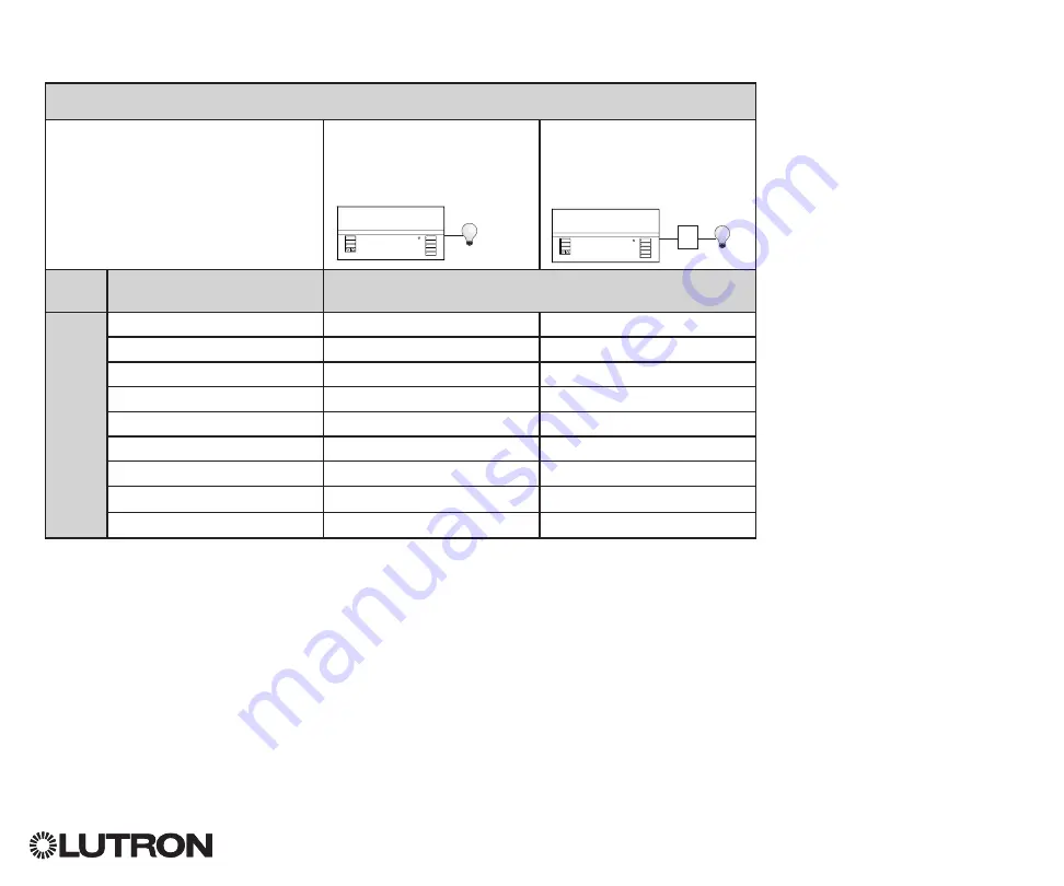
Setting Load Types

Direct control via  

GRAFIK Eye

®

 QS 

control unit

Control via  

power module or 

interface

Fixture load type

Choose this load type from the menu  

on the GRAFIK Eye

®

 QS control unit:

Zones 


– 

6

Incandescent

Incandescent

Power module

MLV (magnetic low-voltage)

MLV

Power module

ELV (electronic low-voltage)

Power module

Hi-lume

®

/Eco-10

®

Fluorescent module

0-10 V

Fluorescent module

Non-dim lighting loads

Non-dim

Non-dim

Neon/Cold cathode

Neon, CC

Neon, CC

DMX

DMX

RGB/CMY DMX

RGB/CMY DMX

Power 

module or 

interface

Summary of Contents for GRAFIK Eye QS

Page 1: ...buttons that are easy to find and operate Model Numbers QSGR 3PCE QSGR 4PCE QSGR 6PCE QSGRK 3PCE QSGRK 4PCE QSGRK 6PCE QSGRM 3PCE QSGRM 4PCE QSGRM 6PCE QSGRN 6PCE QSGRQ 6PCE All units 230 V 50 60 Hz...

Page 2: ...Zone Mode 30 Labeling an Occupancy Sensor optional 31 Configuring Occupancy Sensor Settings optional 32 Daylight Sensor Setup 33 Associating Wireless Daylight Sensors 34 Assigning Sensors 35 Labeling...

Page 3: ...al LEDs maximum of 3 button groups Zone numbers Zone raise lower buttons Zone LEDs display current lighting zone levels Timeclock button Displays current timeclock info OK button Used for programming...

Page 4: ...Mains Wiring 1 2 3 4 1 2 A B C 1 2 3 4 5 6 L N 4 0 mm2 each terminal 230 V Distribution Panel Line Voltage Mains Cables and Load Wiring 1 2 3 4 5 6 L N Incandescent load Load controlled by power modul...

Page 5: ...ceplate overhang on all sides Note 4 gang wallbox available from Lutron P N 241400 Step 2 Test load wiring Turn power OFF at the circuit breaker or fuse box Connect a standard light switch between the...

Page 6: ...damage to unit GRAFIK Eye QS control units must be in stalled by a qual i fied electrician in accordance with all applica ble reg u la tions and building codes Im prop er wiring can result in dam age...

Page 7: ...CCI SIG B 24 V C CCI COM To control stations window treatments or other GRAFIK Eye QS control units Data terminals 3 and 4 Twisted shielded pair 0 5 mm2 each terminal Common and power terminals 1 and...

Page 8: ...ation and Operation Guide 8 Wiring the GRAFIK Eye QS Control Unit QS Link Control Wiring Details QS smart power panel LUTRON LUTRON LUTRON LUTRON LUTRON LUTRON LUTRON LUTRON LUTRON LUTRON LUTRON LUTRO...

Page 9: ...3 and 4 shown by the letter A in the diagram Between devices on the QS link that supply power connect only terminals 1 3 and 4 NOT terminal 2 shown by the letter B on the diagram Wiring can be T tapp...

Page 10: ...ternal 24 V power supply is required to power more than three wallstations To power source QSPS P1 1 50 powers up to 8 seeTouch QS wallstations The Common wire from the power supply connects to QS lin...

Page 11: ...ing IEC PELV NEC Class 2 wiring with line voltage mains wiring 2 Verify installation Restore power Press the top scene button The LED will light Press the zone raise and lower buttons Make sure the co...

Page 12: ...allows fade time adjustment In Save by OK mode pressing a second time allows zone adjustment pressing a third time allows fade adjustment The timeclock button activates the info screen and displays th...

Page 13: ...ming for Sivoia QS window treatments All window treatments fully open All window treatments to 50 All window treatments fully closed Lower Raise all window treatments Applies only to units with shade...

Page 14: ...to toggle between full on and off Press and hold lower for 6 seconds after the zone has gone to 0 light level to set the zone as unaffected in the current scene The zone will not change when this sce...

Page 15: ...on chooses the current highlighted menu choice This will either take you to the next menu or accept a setting you have selected When the screen displays a Yes No question the OK button is Yes Timecloc...

Page 16: ...programming commands from nearby Lutron QS wireless and compatible products Ignore Programming default The GRAFIK Eye QS Wireless control unit will only respond to normal operation commands from wire...

Page 17: ...nes Saved Load Type Assigning Non Dim Load Type Zones assigned to non dim loads have three available configurations LOFO Last On First Off FOFO First On First Off FOLO First On Last Off Scenes made up...

Page 18: ...l zones must be connected however connected zones must have a minimum load of 40 W Maximum loads 10 A per unit 500 W per zone Maximum total lighting load for a magnetic low voltage MLV load is 500 VA...

Page 19: ...gh and low end settings please contact Lutron Technical Support for assistance High and low end trim settings limit the maximum and minimum output of a dimming zone Trim levels are set automatically w...

Page 20: ...zone label to the default e g Zone 1 6 Use the Master buttons to scroll through the characters lowercase and uppercase letters plus numbers 0 through 9 The character you are currently changing will b...

Page 21: ...to indicate this zone is unaffected by the scene the zone will not change when this scene is initiated When all zones are at the desired level press the OK button to accept 5 Use the Master buttons t...

Page 22: ...any remaining characters Press the OK button to accept 7 The info screen will confirm that your name has been saved 8 Exit programming mode Main menu Timeclock Scene setup Labels Select scene Scene 1...

Page 23: ...ing mode 2 Use the Master buttons to highlight Save mode and press the OK button to accept 3 Use the Master buttons to highlight the desired save mode The save modes are listed and explained below 4 P...

Page 24: ...revents the user from making any changes to the control unit The current scene will stay on until the CCI enables normal operation Never Save Prevents any changes from being saved while the CCI is bei...

Page 25: ...open release has no effect Second contact closure ends Afterhours Changing the type of contact closure input 1 Enter programming mode 2 Use the Master buttons to highlight CCI Setup and press the OK...

Page 26: ...control unit Wireless Occupancy Sensor LUTRON LUTRON LUTRON Wireless to Gra LUTRON Wired to QSE IO Wired to Eco dev Wireless to QSM GRAFIK Eye QS control unit QS Sensor Module QSM QS Link Wireless Occ...

Page 27: ...mming from the GRAFIK Eye QS control unit 7 Repeat the above steps for all desired sensors 8 Exit programming mode Associating wireless occupancy sensors through QS Sensor Modules QSM 1 Press and hold...

Page 28: ...n the GRAFIK Eye QS control unit is controlling lights in multiple areas within a room Up to four sensors can be assigned to each zone a sensor can be assigned to more than one zone to send the zones...

Page 29: ...ar with an asterisk in the sensor list Repeat for additional sensors Note If wireless sensors are not found verify that they are associated correctly Setting the Sensor Action 1 Press the Timeclock ba...

Page 30: ...t for additional sensors Note If wireless sensors are not found verify that they are associated correctly Setting the Sensor Action 1 Press the Timeclock back button to return to the Occ Sensor screen...

Page 31: ...to select 6 Use the Master buttons to scroll through the characters lowercase and uppercase letters plus numbers 0 through 9 The character you are currently changing will be underlined on the screen...

Page 32: ...lay Disable this feature by setting the time delay to 0 disabled Range Disabled or 1 30 minutes default Disabled Zone Fade When in Zone Mode lights can be set to fade to the unoccupied levels over thi...

Page 33: ...ik Eye Wired to QSM Wired to Eco device Wireless to QSM LUTRON LUTRON LUTRON LUTRON LUTRON LUTRON Wireless to Grafik Eye Wired to QSM Wired to Eco device Wireless to QSM LUTRON LUTRON LUTRON LUTRON LU...

Page 34: ...ionality Doing so will remove its programming from the GRAFIK Eye QS control unit 7 Repeat the above steps for all desired sensors 8 Exit programming mode Associating wireless daylight sensors through...

Page 35: ...ss Radio Powr SavrTM daylight sensors associated with the desired zones into Calibrate Mode Press and hold the Cal button for 6 seconds until the sensor flashes Note After 5 minutes Calibrate Mode wil...

Page 36: ...ect 6 Use the Master buttons to scroll through the characters lowercase and uppercase letters plus numbers 0 through 9 The character you are currently changing will be underlined on the screen Press O...

Page 37: ...nction Scene Function Top On Button All assigned zones 100 Scene 1 Center Preset Button if available All assigned zones at programmed preset level Press and hold to save current levels on assigned zon...

Page 38: ...ns simultaneously for 1 second until the zone LEDs flash at the programmed preset level Repeat for all zones you wish to control with the Pico wireless control OR 3b To assign the Pico wireless contro...

Page 39: ...to select the desired operation mode for the Pico wireless control 5a To assign the Pico wireless control as a zone controller use the Master buttons to select Zone and press the OK button to accept...

Page 40: ...RAFIK Eye QS control unit through the QS IR Eye or a Lutron IR receiver wired to a QS Sensor Module QSM to control the light level of a specific zone or to act as a scene controller The QS IR Eye and...

Page 41: ...p and press the OK button to accept 3 Use the Master buttons to highlight Integral IR and press the OK button to accept 4 Use the Master buttons to highlight either Enabled or Disabled and press the O...

Page 42: ...ed Press the OK button to continue 3 Use the Master buttons to select Scene and press the OK button to accept 4 Use the Master buttons to select one of the scene control types listed below to correspo...

Page 43: ...QS IR Eye The info screen will confirm that your settings have been saved OR 2b To assign the QS IR Eye as a scene controller use the Master buttons to select Scene and press the OK button to accept...

Page 44: ...Zone and press the OK button to accept Use the zone raise lower buttons for a zone to select a desired preset level then press the zone raise and lower buttons simultaneously for 1 second until the zo...

Page 45: ...Sivoia QS Wireless window treatment EDU LED For Wireless Sivoia QS Window Treatments To associate window treatments with a shade button group 1 Make sure the wireless mode of the GRAFIK Eye QS control...

Page 46: ...in the opposite order 3 Adjust the currently selected EDU to the desired level for the open limit the maximum the window treatment is allowed to open using the raise and lower buttons 4 Press and hold...

Page 47: ...assigned window treatments will move to their closed limits and EDUs for unassigned window treatments will move to their open limits 2 Press and release the middle button on that shade button group T...

Page 48: ...om and press the OK button to accept 5 Use the Master buttons to scroll through the characters lowercase and uppercase letters plus numbers 0 through 9 The character you are currently changing will be...

Page 49: ...bled Note The wireless signal has a range of 9 m through standard construction or 18 m line of sight To associate two GRAFIK Eye QS control units 1 Begin with the GRAFIK Eye QS control unit that will...

Page 50: ...s the OK button to accept 5 Use the Master buttons to highlight the current hour and press the OK button to accept Repeat for the current minutes 6 Use the Master buttons to highlight the current year...

Page 51: ...llation and Operation Guide 51 Timeclock Operation Setting Location 1 Enter programming mode 2 Use the Master buttons to highlight Timeclock and press the OK button to accept 3 Use the Master buttons...

Page 52: ...ing the space it controls 6 Use the Master buttons to highlight the type of the event fixed time of day or a relative time to sunrise or sunset Press the OK button to accept 7 For a fixed time event u...

Page 53: ...e otherwise press the timeclock button to go back 7 The info screen will confirm that your event has been deleted 8 Exit programming mode Main menu Timeclock Scene setup Timeclock Copy schedule Timecl...

Page 54: ...utton Timeclock Delete schedule Holiday Add event View holiday Set holiday Holiday Set holiday 1 25 1 Feb Monday Set holiday 1 25 Feb 14 Deleting a Holiday 1 Enter programming mode select Timeclock se...

Page 55: ...ents occurring on the selected day to copy to press the OK button to accept 7 Exit programming mode OK 1 2 3 4 5 6 Master buttons OK button Timeclock Delete schedule Delete events Copy schedule Copy f...

Page 56: ...start the Afterhours feature even if it receives commands from a Timeclock event contact closure input or another device on the QS link Note The Afterhours feature must be programmed to start or end t...

Page 57: ...s Office worker Button press Office worker Button press Security guard Delay time lights flash Delay time lights flash Delay time lights flash Warn Time Warn Time Warn Time Delay time Afterhours Scene...

Page 58: ...utton to accept each setting The info screen will confirm that your Afterhours settings have been saved 6 Exit programming mode OK 1 2 3 4 5 6 Master buttons OK button Afterhours Enabled Flash count 3...

Page 59: ...de and select Backlighting Press the OK button to accept 2 Use the Master buttons to highlight either Enabled or Disabled Press the OK button to accept The info screen will confirm that your setting h...

Page 60: ...The character you are currently changing in the password will appear underlined on the info screen Press OK to select the desired character and repeat for the remaining characters The info screen will...

Page 61: ...language and press the OK button to select and save Faceplate Removal The faceplates may need to be removed to change the color or to write in zone labels To remove either faceplate open it fully flu...

Page 62: ...tion is required Unit does not allow scene change or zone adjustments Unit is in wrong save mode Change to correct save mode QS device in system has locked the unit Check programming and state of QS d...

Page 63: ...wireless devices do not control unit Wireless device has been unassigned from unit Reassign wireless device to unit Devices are not receiving power Check wireless device s battery power wiring Unit i...

Page 64: ...ught on something Check and unbind window treatment fabric Window treatment moves in the opposite direction when raise lower buttons are pushed Open and close limits have been reversed Set limits corr...

Page 65: ...KEN WITHOUT LUTRON S WRITTEN CONSENT ARISING OUT OF OR IN ANY WAY RELATED TO THE INSTALLATION DEINSTALLATION USE OF OR INABILITY TO USE THE UNIT OR OTHERWISE UNDER OR IN CONNECTION WITH ANY PROVISION...

Reviews: