


LUTRON
Control Unit
Installation and Operation Guide
®
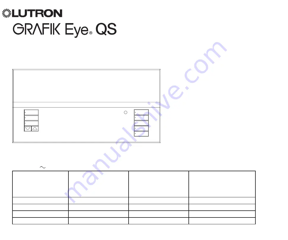
Please Read
The GRAFIK Eye
®
QS control unit allows
for control of both lights and window
treatments, without interfaces, using
a single control unit. Features include
pushbutton scene recall, info screen
that displays energy savings and status,
IR receiver, astronomic timeclock, contact
closure input, and engravable backlit
buttons that are easy to find and operate.
Model Numbers: QSGR-3PCE, QSGR-4PCE, QSGR-6PCE
QSGRK-3PCE, QSGRK-4PCE, QSGRK-6PCE
QSGRM-3PCE, QSGRM-4PCE, QSGRM-6PCE
QSGRN-6PCE, QSGRQ-6PCE
All units 230 V
50/60 Hz
QSGR-3PCE
QSGRK-3PCE
QSGRM-3PCE
QSGR-4PCE
QSGRK-4PCE
QSGRM-4PCE
QSGR-6PCE
QSGRK-6PCE
QSGRM-6PCE
QSGRN-6PCE
QSGRQ-6PCE
Unit Capacity (watts)
1 500 W
2 000 W
2 300 W
MLV
1 500 VA / 1 200 W
2 000 VA / 1 600 W
2 300 VA / 1 800 W
Zone Capacity (watts)
40 – 500 W
40 – 500 W
40 – 500 W
MLV
40 – 500 VA / 40 – 400 W
40 – 500 VA / 40 – 400 W
40 – 500 VA / 40 – 400 W
See page 8 for IEC PELV/NEC
®
Class 2 ratings.


