4-64
Engineering Guide CDA3000
4 Software functions
(ASTER = M-S3)
Master-/Slave operation (configuration 14)
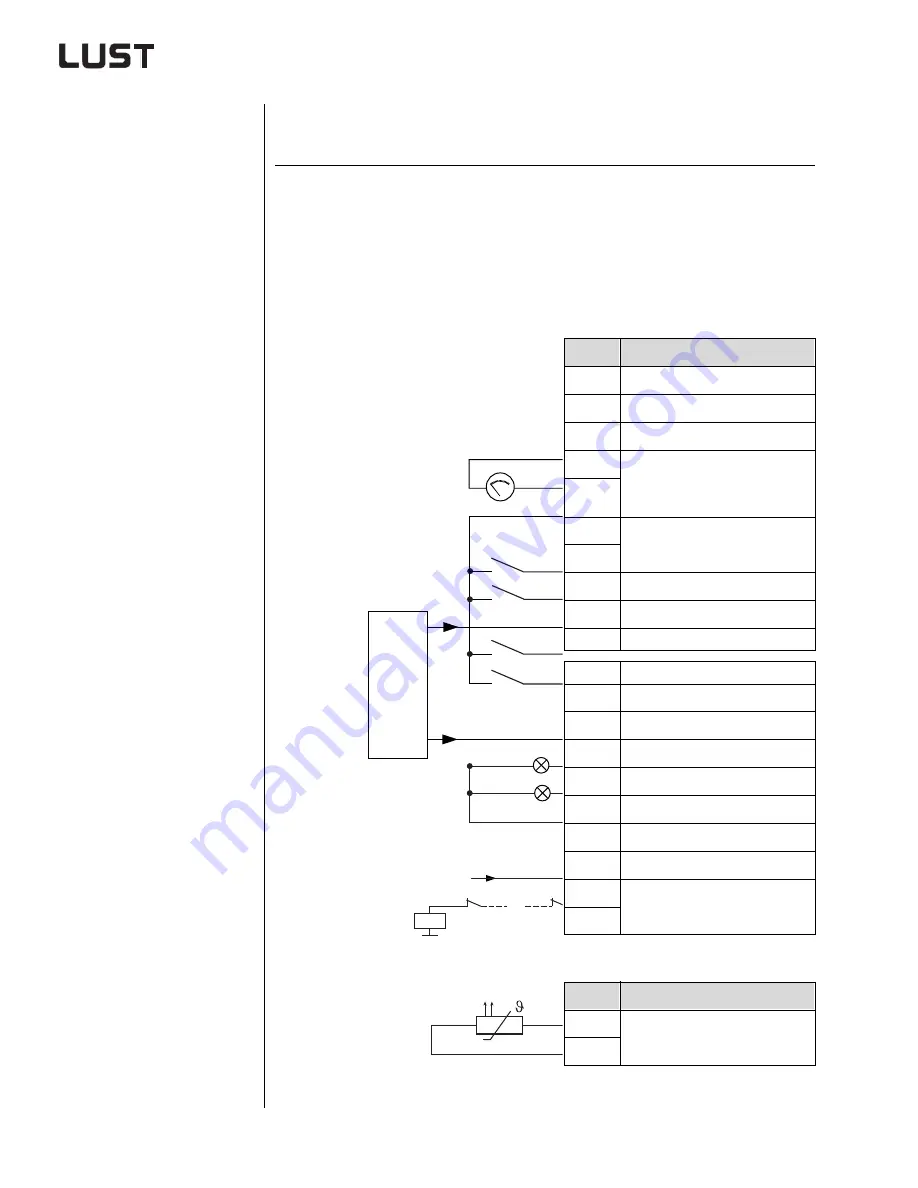
Figure 4.53
Control terminal assignment with ASTER = M-S3; with S1 and
S2 an offset can be added to or subtracted from the guide value
Function
Application
•
Speed synchronism of several drives
with programmable transmission
ratio
•
Inverter module is slave
•
Adjustment of guide value via button
(MOP function)
•
Replacement of mechanical gears
and line shafts (not angle-synchro-
nous)
•
Winding drive
•
Drafting equipment
•
Trolley drive
X2
Function
1
Reference voltage 10 V, 10 mA
2
Reference -10 V ... + 10 V
3
not assigned
4
Actual frequency
0 ... 10 V corresponding to
0 ... FMAX
5
6
Auxiliary voltage 24 V max.
200 mA
7
8
Power stage hardware enable
9
Start/Stop clockwise
10
Master interface
11
Increase speed
12
Reduce speed
13
Auxiliary voltage 24 V
14
Digital ground
15
“Reference reached” message
16
Message: Standstill
17
Digital ground
18
Relay contact (break)
19
Relay contact (make)
for "ready" signal
20
X3
Function
1
Motor PTC evaluation
Function inactive
2
K0
H2
H1
N1
S2
ENPO
STR
STL
S1
Master


