


Ring Setup and Testing: Integration Procedures
Fiber Installation
...........................................................................................................................................................................................................................................................
6 - 7
Lucent Technologies - Proprietary
See notice on first page
365-372-327 R2.0
Issue 1, October 2003
............................................................................................................................................................................
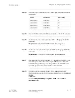
Step 13
Select the proper LBO based on the value required and the comcode as
listed below.
............................................................................................................................................................................
Step 14
Clean LC LBOs and install LBO assemblies in the OLIU IN connector.
............................................................................................................................................................................
Step 15
At the far end, connect the input optical fiber to the proper OLIU IN
connector.
Requirement:
The FAULT LED on the OLIU extinguishes.
............................................................................................................................................................................
Step 16
At the near end, connect the input optical fiber to the proper OLIU IN
connector.
Requirement:
The FAULT LED on the OLIU extinguishes.
............................................................................................................................................................................
Step 17
Disconnect the fiber cable from the OUT connector on the OLIU at one
end of the span. At the other end, verify that the associated FAULT
LED is flashing, indicating a loss of signal. Reconnect the fiber and
repeat the process for the other direction of transmission.
............................................................................................................................................................................
Step 18
In order to enable communications with the adjacent Metropolis
®
DMXtend nodes, execute the following command from the
Command
Builder
.
ent-fecom
Choose
COM={ENABLED} verify M1 = USER side and M2 =
NETWORK side
Code
Comcode
Loss (dB)
ABLCS-05.0
108279381
5
ABLCS-10.0
108279431
10
ABLCS-15.0
108279480
15
ABLCS-20.0
108279530
20


