


...........................................................................................................................................................................................................................................................
Ring Setup and Testing: Integration Procedures
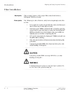
Fiber Installation
6 - 6
Lucent Technologies - Proprietary
See notice on first page
365-372-327 R2.0
Issue 1, October 2003
until at least 45 seconds after an optical loopback is removed. It
may take from 15 seconds to 3.5 minutes for the FAULT LEDs to
stop flashing after the cables are connected, depending on the
setting of the OC-3/OC-12 signal degrade threshold.
............................................................................................................................................................................
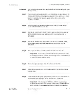
Step 9
At both ends of the optical span, ensure that only the dual LC adapter is
installed on the OLIU (no LBO).
Important!
For Metropolis
®
DMXtend OC-3/OC-12 ring
configurations, optical fibers extend in two different directions to
make up the ring. At each shelf (node) in the ring, the M1 OLIU
will connect to the M2 OLIU in one adjacent node, and the M2
OLIU will connect to the M1 OLIU in the other adjacent node.
Likewise, when the Metropolis
®
DMXtend is interfacing with other
equipment at low-speeds (OC-3 or OC-12) (R1.1) using 0x1
protection, the Function Group slot (D, or G) 1 will connect to
Main 2 on whatever shelf the Metropolis
®
DMXtend is being
connected to. The Function Group slot (D, or G) 2 will connect to
Main 1.
............................................................................................................................................................................
Step 10
At each end of the optical span, connect the optical fiber transmit
cables to the OLIU OUT connectors.
............................................................................................................................................................................
Step 11
At each end of the optical span, measure the optical power of the
optical fiber receive cables using an optical power meter.
............................................................................................................................................................................
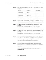
Step 12
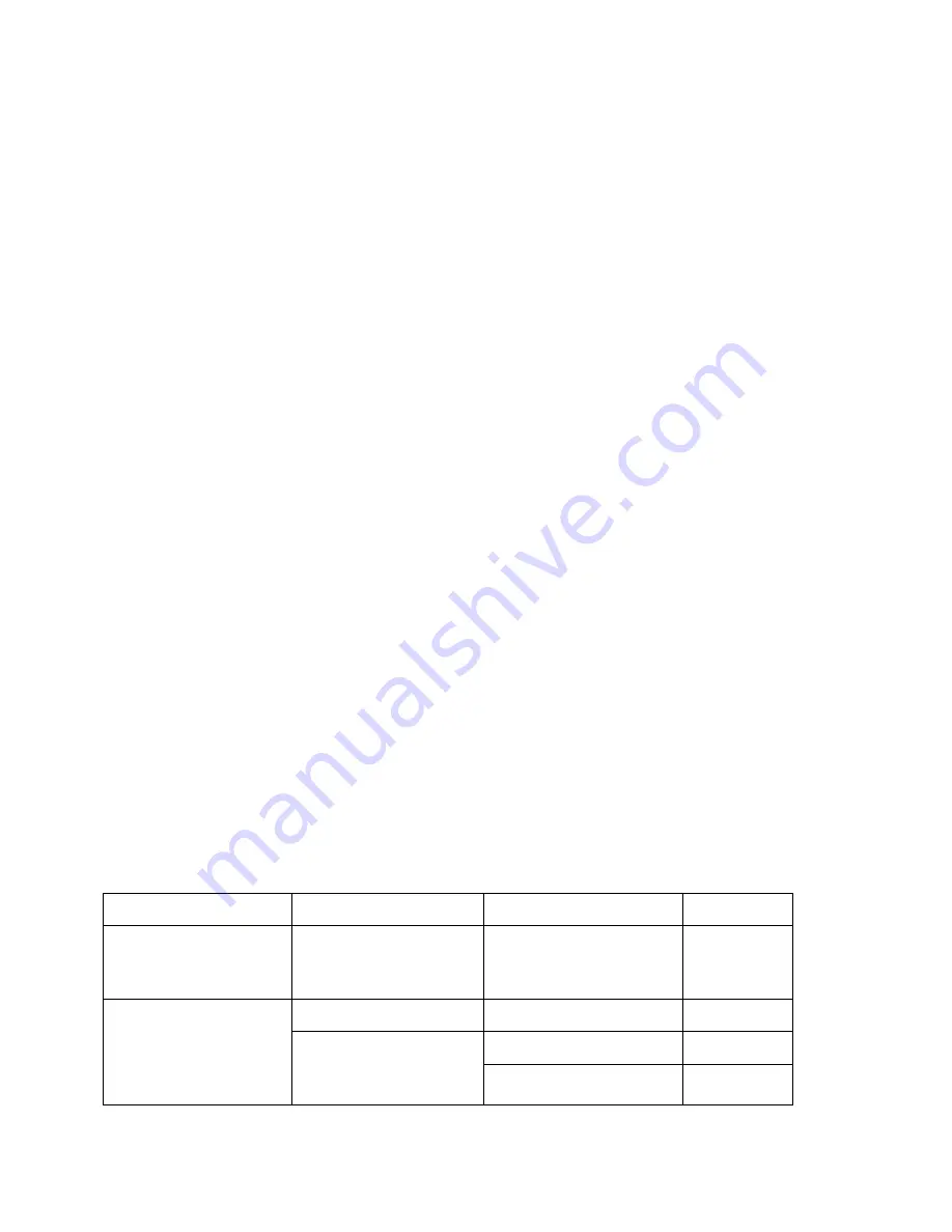
Determine the LBO value required based on the received optical power
measurement. Refer to the following table.
Optics
Circuit Pack
Received Power(dBM)
LBO (dB)
Intermediate Reach (IR)
Optics
LNW40 OC-3
LNW38 OC-12
-8.0 to -28.0
0
Long Reach (LR) Optics
LNW 36 OC3 (R1.1)
0.0 to -34.0
0
LNW46 OC12 (R1.1)
LNW51 OC-12 (R1.1)
+2.0 to -8.0
10
-8.0 to -30.0
0


