


Doc: I378RUGB05_16.doc
10/02/2014
p. 13 / 43
ИК
порт
программирования
Настройку
параметров
прибора
RGK6..
можно
осуществлять
с
помощью
расположенного
на
его
передней
панели
оптического
порта
с
использованием
ключа
USB CX01
или
ключа
WiFi CX02.
Этот
порт
программирования
обладает
следующими
преимуществами
:
o
Он
позволяет
осуществлять
конфигурирование
и
техобслуживание
прибора
RGK6..
без
необходимости
доступа
к
его
задней
панели
и
,
следовательно
,
без
открывания
электрического
шкафа
.
o
Он
гальванически
изолирован
от
внутренних
цепей
RGK6..,
что
гарантирует
максимум
безопасности
для
оператора
.
o
Обеспечивает
высокую
скорость
передачи
данных
.
o
Обеспечивает
с
передней
стороны
класс
защиты
IP65.
o
Ограничивает
возможность
несанкционированного
доступа
к
настройкам
прибора
.
При
присоединении
ключа
CX..
к
оптическому
порту
на
передней
панели
прибора
и
установке
разъемов
в
соответствующие
ответные
части
произойдет
взаимное
распознавание
устройств
,
в
подтверждение
чего
загорится
зеленый
светодиод
LED LINK
на
ключе
.
IR programming port
The parameters of the RGK6.. can be configured through the front optical
port, using the IR-USB CX01 programming dongle, or with the IR-WiFi
CX02 dongle.
This programming port has the following advantages:
o
You can configure and service the RGK6.. without access to the rear
of the device or having to open the electrical board.
o
It is galvanically isolated from the internal circuits of the RGK6..,
guaranteeing the greatest safety for the operator.
o
High speed data transfer.
o
Ip65 front panel.
o
Limits the possibility of unauthorized access with device config.
Simply hold the CX.. dongle up to the front panel, connecting the plugs to
the relevant connectors, and the device will be acknowledged as shown
by the LINK LED on the programming dongle flashing green.
Настройка
параметров
с
ПК
С
помощью
ПО
настройки
Customization manager
можно
осуществить
перенос
параметров
настройки
(
ранее
заданных
)
с
RGK6..
на
диск
ПК
и
наоборот
.
Перенос
параметров
с
ПК
на
RGK
может
быть
частичным
,
то
есть
можно
переносить
только
указанные
оператором
параметры
.
Кроме
параметров
,
с
помощью
ПК
можно
задать
:
o
Данные
,
относящиеся
к
характеристикам
кривых
датчиков
давления
,
температуры
,
уровня
топлива
и
устройств
тепловой
защиты
генератора
.
o
Персонализированный
логотип
,
который
выводится
на
дисплей
при
подаче
питания
на
прибор
,
а
также
всякий
раз
,
когда
выполняется
выход
из
меню
настроек
с
клавиатуры
.
o
Информационную
страницу
,
на
которую
можно
внести
информацию
,
данные
и
характеристики
,
относящиеся
к
системе
.
o
Загрузку
комплекта
языков
,
отличных
от
заданных
по
умолчанию
.
Настройка
параметров
(setup)
с
помощью
клавиш
,
расположенных
на
передней
панели
.
Для
входа
в
меню
настройки
параметров
(setup):
o
Установите
прибор
в
режим
STOP/RESET
o
Находясь
в
обычном
режиме
измерений
,
одновременно
нажмите
▲
и
▼
для
вывода
на
дисплей
Главного
меню
o
Выберите
символ
.
Если
этот
символ
не
активирован
(
выводится
серым
),
это
означает
,
что
необходимо
ввести
пароль
для
разблокировки
системы
(
см
.
главу
"
Доступ
с
помощью
пароля
"
).
o
Нажмите
,
чтобы
войти
в
меню
настроек
.
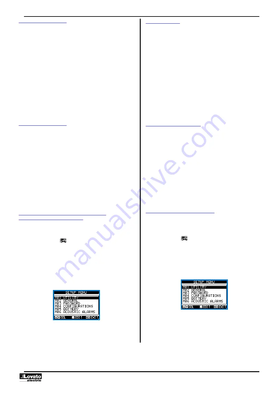
На
дисплее
появится
показанная
на
рисунке
таблица
подменю
настроек
,
объединяющих
все
параметры
на
основе
их
функций
.
Выберите
нужное
меню
с
помощью
клавиш
▲
или
▼
и
подтвердите
нажатием
.
Для
выхода
и
возврата
в
режим
визуализации
измерений
нажмите
STOP
.
Настройка
:
выбор
меню
В
следующей
ниже
таблице
перечислены
доступные
подменю
:
Parameter setting (setup) with PC
You can use the
Customization manager
set-up software to transfer
(previously programmed) set-up parameters from the RGK6.. to the hard
drive of the PC and vice versa.
The parameter may be partially transferred from the PC to the RGK,
transferring only the parameters of the specified menus.
The PC can be used to set parameters and also the following:
o
Data on the characteristics of the pressure, temperature, fuel level
sensor curves, and the generator protection
o
Customised logo displayed on power-up and every time you exit
keyboard setup.
o
Info page where you can enter application information,
characteristics, data, etc.
o
Load alternative set of languages to default.
Parameter setting (setup) from front panel
To open the parameters programming menu (setup):
o
Turn the unit in
STOP/RESET
mode
o
In normal measurements view, press
▲▼
simultaneously to call up
the
Main menu
o
Select the icon
. If it is disabled (displayed in grey) you must
enter the password (see chapter
Password access
).
o
Press
to open the setup menu.
The table shown in the illustration is displayed, with the settings sub-
menus of all the parameters on the basis of their function.
Select the required menu with keys
▲
or
▼
and confirm with
.
Press
STOP
to return to the valves view.
Settings: menu selection
The following table lists the available submenus:


