


Chapter 7 GENERAL DESCRIPTION
7 - 17
GT 112-E
7.12 RETRACTION DEVICE (Option)
It is strictly prohibited to use the retraction system before the bar
feeder is anchored to the ground. Please read the safety instructions
provided at the beginning of this manual before handling the
following devices.
Before handling the retraction mechanism, make sure the interface
cables between the spindle and the bar feeder have enough slack.
7.12.1 Description
When a lathe is equipped with a bar feeder, certain elements (motors, spindle reduction tubes,
etc.) become inaccessible, and sometimes it is difficult, or even impossible, to proceed with their
maintenance. Changing spindle liners on fixed headstock machines could also be a challenge.
To facilitate these tasks, the bar feeder can be equipped with a retraction system, which allows
the operator to move it away from the lathe. The rigidity of the system guarantees a perfect
alignment when the bar feeder is in working position. Safety switches impede any handling as
long as the bar feeder is not in operational position.
7.12.2 Operation
Conditions:
- Bar feeder in MANUAL or STOP mode.
- No bar between the bar feeder and the lathe
- Pusher inside the bar feeder
- The area around the bar feeder must be clear
Procedure:
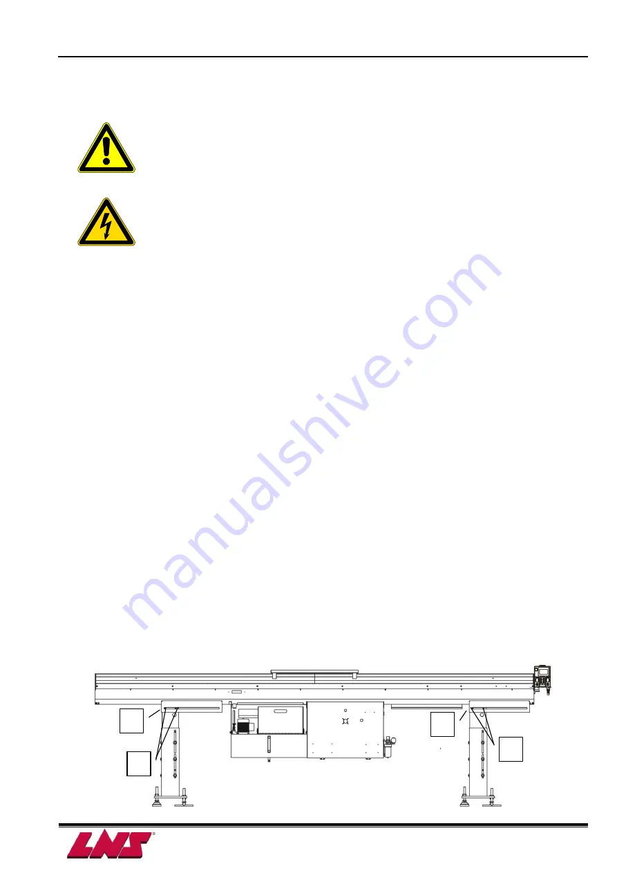
1. Loosen the 8 lock bolts (A) on the two stands. 4 bolts on each side of the bar feeder.
2. Loosen and remove the 4 lock screws (B) behind the two stands.
3. Pull the bar feeder back by hand as the upper part of the bar feeder slides easily on the
roller bearings. The safety switch SQ10 will engage (Refer to chapter 4.6)
4. After completing the maintenance operations, bring the bar feeder back in the forward
working position, secure with lock screw (B) and tighten the side screws (A) (max. 75 Nm).
A
B
A
B
Summary of Contents for GT 112-E
Page 7: ...1 4 Chapter 1 BASIC NOTIONS GT 112 E...
Page 10: ...Chapter 2 TECHNICAL DATA 2 3 GT 112 E 2 4 FLOOR PLAN LtoRF Bar Feeder...
Page 11: ...2 4 Chapter 2 TECHNICAL DATA GT 112 E RtoLF Bar Feeder...
Page 13: ...2 6 Chapter 2 TECHNICAL DATA GT 112 E...
Page 21: ...3 8 Chapter 3 SETTING INTO OPERATION GT 112 E...
Page 32: ...Chapter 4 ELECTRICS 4 11 GT 112 E 4 4 PLC I O Circuit diagram XM1 25 A001G...
Page 33: ...4 12 Chapter 4 ELECTRICS GT 112 E 4 5 DIAGRAMS 4 5 1 AC circuit Circuit diagram XM1 25 A001G...
Page 34: ...Chapter 4 ELECTRICS 4 13 GT 112 E 4 5 2 Emergency stop circuit Circuit diagram XM1 25 A001G...
Page 35: ...4 14 Chapter 4 ELECTRICS GT 112 E Circuit diagram XM1 25 A001G...
Page 36: ...Chapter 4 ELECTRICS 4 15 GT 112 E Circuit diagram XM1 25 A001G Option...
Page 38: ...Chapter 4 ELECTRICS 4 17 GT 112 E Interface diagram BXA00001...
Page 48: ...Chapter 5 PNEUMATICS 5 7 GT 112 E 5 5 PNEUMATIC DIAGRAMS Pneumatic diagrams XM1 27 P003A...
Page 49: ...5 8 Chapter 5 PNEUMATICS GT 112 E Pneumatic diagrams XM1 27 P003A...
Page 50: ...Chapter 5 PNEUMATICS 5 9 GT 112 E Pneumatic diagrams XM1 27 P003A...
Page 51: ...5 10 Chapter 5 PNEUMATICS GT 112 E...
Page 75: ...7 20 Chapter 7 GENERAL DESCRIPTION GT 112 E...
Page 110: ...Chapter 8 OPERATION 8 35 GT 112 E 1 Start loading signal A3 2 Push signal A4...
Page 111: ...8 36 Chapter 8 OPERATION GT 112 E...
Page 114: ...Chapter 8 OPERATION 8 39 GT 112 E...
Page 150: ...9 36 Chapter 9 TROUBLE SHOOTING GUIDE GT 112 E...
Page 153: ...Chapter 10 APPENDICES 10 3 GT 112 E APPENDIX C ADDRESS LNS LNS Japan www lns japan com...
Page 154: ...10 4 Chapter 10 APPENDICES GT 112 E...
Page 155: ...XM1 00 A501B GT 112 E A 1...


