Chapter 8 OPERATION
8 - 5
GT 112-E
8.2
POWERING AND EMERGENCY STOP
8.2.1
Powering up
The main power is supplied by the interface cable. Before connecting the interface cable to the
lathe, make sure the power supply meets the interface specifications.
Depending on the power supplied by the lathe a Transformer (optional) may be needed.
The power supplied to the bar feeder should be protected by a circuit-breaker (6A max) located
in the lathe.
The servo motor of bar feeder is equipped with a built-in absolute encoder that continuously
controls the position of the carrier. When the bar feeder is powered down or there is a power
failure, this position is kept in the memory by the PLC.
When powering up, the pusher position value saved is immediately taken into account. The PLC
reads signals from sensors and gives the operator allowable operations only.
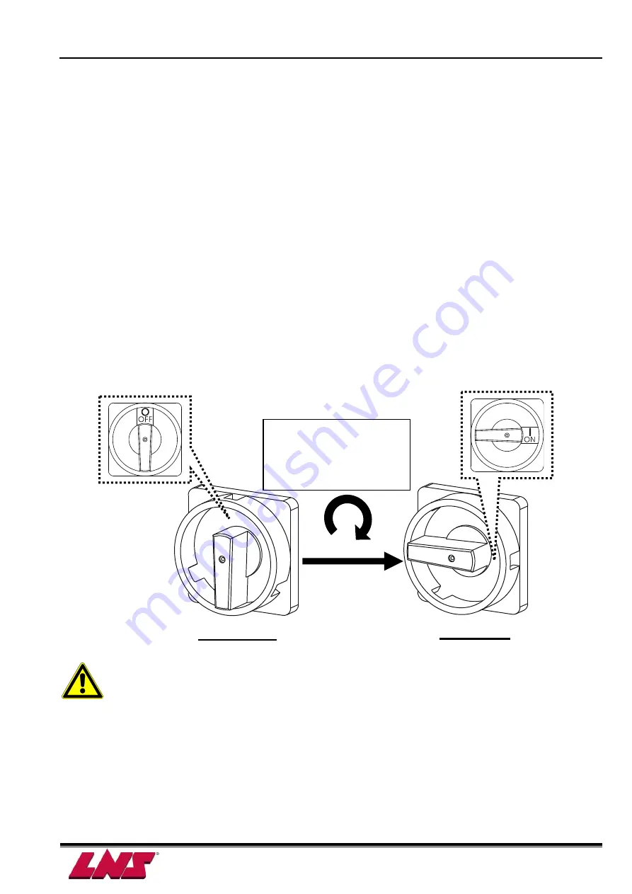
Main disconnect switch QS1
Make sure it is turned OFF before opening the electrical cabinet.
Do not move or change the pusher position by hand when bar feeder is
powered OFF.
In case the pusher was accidently moved before powering down move the
pusher back to its home position. Turn the bar feeder OFF and power back
up.
Power ON
Power OFF
Turn the button
clockwise to power UP
the bar feeder.
Summary of Contents for GT 112-E
Page 7: ...1 4 Chapter 1 BASIC NOTIONS GT 112 E...
Page 10: ...Chapter 2 TECHNICAL DATA 2 3 GT 112 E 2 4 FLOOR PLAN LtoRF Bar Feeder...
Page 11: ...2 4 Chapter 2 TECHNICAL DATA GT 112 E RtoLF Bar Feeder...
Page 13: ...2 6 Chapter 2 TECHNICAL DATA GT 112 E...
Page 21: ...3 8 Chapter 3 SETTING INTO OPERATION GT 112 E...
Page 32: ...Chapter 4 ELECTRICS 4 11 GT 112 E 4 4 PLC I O Circuit diagram XM1 25 A001G...
Page 33: ...4 12 Chapter 4 ELECTRICS GT 112 E 4 5 DIAGRAMS 4 5 1 AC circuit Circuit diagram XM1 25 A001G...
Page 34: ...Chapter 4 ELECTRICS 4 13 GT 112 E 4 5 2 Emergency stop circuit Circuit diagram XM1 25 A001G...
Page 35: ...4 14 Chapter 4 ELECTRICS GT 112 E Circuit diagram XM1 25 A001G...
Page 36: ...Chapter 4 ELECTRICS 4 15 GT 112 E Circuit diagram XM1 25 A001G Option...
Page 38: ...Chapter 4 ELECTRICS 4 17 GT 112 E Interface diagram BXA00001...
Page 48: ...Chapter 5 PNEUMATICS 5 7 GT 112 E 5 5 PNEUMATIC DIAGRAMS Pneumatic diagrams XM1 27 P003A...
Page 49: ...5 8 Chapter 5 PNEUMATICS GT 112 E Pneumatic diagrams XM1 27 P003A...
Page 50: ...Chapter 5 PNEUMATICS 5 9 GT 112 E Pneumatic diagrams XM1 27 P003A...
Page 51: ...5 10 Chapter 5 PNEUMATICS GT 112 E...
Page 75: ...7 20 Chapter 7 GENERAL DESCRIPTION GT 112 E...
Page 110: ...Chapter 8 OPERATION 8 35 GT 112 E 1 Start loading signal A3 2 Push signal A4...
Page 111: ...8 36 Chapter 8 OPERATION GT 112 E...
Page 114: ...Chapter 8 OPERATION 8 39 GT 112 E...
Page 150: ...9 36 Chapter 9 TROUBLE SHOOTING GUIDE GT 112 E...
Page 153: ...Chapter 10 APPENDICES 10 3 GT 112 E APPENDIX C ADDRESS LNS LNS Japan www lns japan com...
Page 154: ...10 4 Chapter 10 APPENDICES GT 112 E...
Page 155: ...XM1 00 A501B GT 112 E A 1...


