


Motion Control SW
L
i
n
M
o
t
7 Drive Configuration
The parameter configuration is normally done with Lintalk1100-SW [3]. The UPIDs, over
which the parameter can be accessed, are different for the B1100 drives. In this
documentation the E1100 UPIDs are used. If a UPID for a B1100 drive is needed, a
conversion list can be generated with the Lintalk1100-SW.
7.1 Power Bridge
The E1100/B1100 drives are divided into three different power classes. The normal drives
have a maximal current of 8A, the high current (name extension HC) variant has a maximal
current of 15A and the extreme current (name extension XC) has a maximal current of 25A.
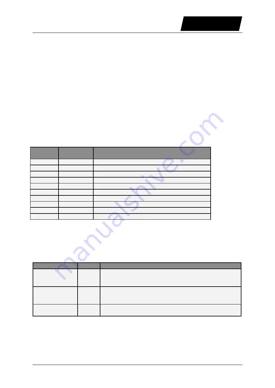
7.2 X4 I/O Definitions
The functionality of most IOs can be programmed as a control word input bit or status word
output bit, or they can be used as interface IO and read out or written over a serial bus
interface. Apart from this general functionality a few IOs have a special functionality.
Descriptor General
Purpose IO
Special Functions
X4.3
Yes
Brake (Output)
X4.4
Yes
Analog In
X4.5
Yes
Capture Input
X4.6
Yes
Trigger (Input)
X4.7
Yes
Home Switch (Input)
X4.8
Yes
Limit IN (Input)
X4.9
Yes
Limit OUT (Input) / 24V Step (Input)
X4.10
Yes
PTC 1 (Input) / 24V Direction (Input)
X4.11
Yes
PTC 2 (Input)
X4.12
No
SVE Safety Voltage Enable (Input)
7.2.1 X4.3 Brake
The output X4.3 can drive up to 1A, so it can be used to control directly a valve of a
pneumatic brake module. For this reason this output can be configured as brake output. The
cases in which the brake has to be applied or released are configured over the brake mode
parameters. The brake output is controlled from the state machine.
Parameter Name
UPID
Description
Status Word:
Operation
Enabled
1717h
The brake is released (X4.3 = 24V), when bit 0 of the status
word (Operation Enabled) is set. Otherwise the brake is
applied.
Ctrl Word: /Abort
1718h
The brake is applied (X4.3 = 0V) when entering the Aborting
State (12) and released (X4.3 = 24V) when going to
Operation Enabled State (8) again.
Quick Stop
1716h
Special brake behavior with Quick Stop (Brake Mode Status
Word: Operation Enabled has also to be set)
NTI AG / LinMot
User Manual Motion Control SW/ 06/12/2013
Page 71/91